Case study – Lice skirt
Last reviewed version: 2.22For the next steps, you may use the AquaSim model LiceSkirt.amodel, following this tutorial. You are to finish the model by inputting appropriate parameters to the lice skirt.
The model contains a classical configuration with a PE floating collar and a permeable net mounted in a frame anchoring system. Attached to the net, is the lice skirt. The lice skirt is modelled with membrane type Normal in combination with Load formulation Lice skirt.
Double click on the component type 6 Lice skirt, in the components window, and navigate to the Load properties tab. This tab provides input parameters that is relevant for the type of dense fabrics as lice skirt.
In the next sections, the different parameters are presented – what they mean and how they can be used. Please note that the values of the presented input-parameters are not definitive requirements. It is acknowledged that there is very limited empirical data available for these types of structures. So, the user must also assess the values based on experience with expected response of the tarpaulin and load distribution. The presented values should be treated as indicative guidance rather than fixed recommendations.
Because empirical data is limited, a degree of uncertainty must be expected. However, the uncertainty may me reduced by considering a range of values for the parameters by conducting sensitivity studies and evaluate how the different parameters influence the overall response and load distribution on the tarpaulin.
Fluid parameters internally in tank
The Fluid parameters inside tank specifies the properties of the fluid enclosed by a structure. These parameters define how much of the fluid that should be set into motion when the structure is exposed to waves and current.
For lice skirts these parameters is recommended to be set to 0.0. This is because a lice skirt does not trap or confine any internal fluid. The bottom is open through the permeable net below, so the fluid is free to move. These parameters become relevant in the case of fully or partially closed volumes.
Drag
This part of the Impermeable properties regulates the magnitude of pressure drag, skin friction drag and lift forces acting on the lice skirt. Before discussing these coefficients, it is useful to understand how the fluid flow behaves when it passes the skirt.
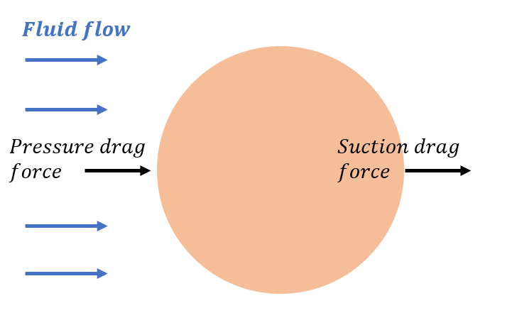
The figure below illustrates the lice skirt seen from above. When fluid flow approaches the lice skirt, it meets a solid barrier. On the upstream side, the fluid slows down and creates a high-pressure region. This is where the largest drag force occurs. As the flow moves around the sides of the skirt, it will start to accelerate along the surface, which will increase the skin friction drag.
Further downstream, the fluid cannot stay attached to the surface any longer and it separates. A region of turbulent wake is created behind the skirt. In this wake region the fluid loses momentum, and energy is dissipated into turbulence, leading to a low-pressure region. This is why suction drag downstream is smaller than the pressure drag on the upstream side.
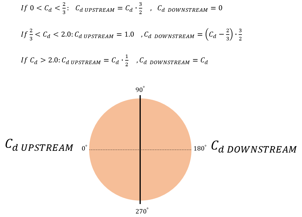
Since AquaSim keeps track of where the panels are situated with respect to each other, it is possible to assign drag coefficients upstream and downstream with respect to incoming wave and current.
Drag coefficient upstream
AquaSim decompose the relative velocity (between the lice skirt and fluid) into a normal and tangential component, as illustrated below. The normal component of the relative velocity is applied in the calculation of pressure drag. The Drag coefficient upstream scales this force for panels located upstream.
In this case, this parameter is set to 1.0.
Drag coefficient downstream
As mentioned above, AquaSim decompose the relative velocity into a normal and tangential component. The normal component of the relative velocity downstream is applied in the calculation of suction drag. The Drag coefficient downstream scales this force for panels located downstream.
In this case, this parameter is set to 0.5. The drag coefficient downstream on the lice skirt is lower than the upstream because of flow separation. When the flow passes the impermeable lice skirt, the flow will separate. The consequence is that the fluid loose momentum, which results in reduced pressure on the downstream panels.
Skin friction coefficient
Skin friction force arises due to fluid particles tend to “stick” to the surface. The magnitude of this force often depends on fluid viscosity and surface roughness. The Skin friction coefficient regulates the magnitude of the skin friction force. In AquaSim this force is calculated applying the tangential relative velocity.
In this tutorial, skin friction coefficient is set to 0.05.
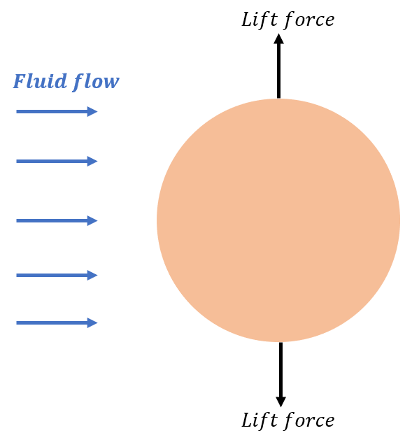
Lift coefficient
The Lift coefficient scales the lift force that acts perpendicular to the fluid flow direction. Lift force arises when a flow around a structure is asymmetric, creating a pressure difference between structure sides. AquaSim apply the normal component of the relative velocity, as well as the total relative velocity, to calculate the lift force on a panel.
In our case, the Lift coefficient is set to 1.0.
Wave excitation load
This section presents the input parameters for wave induced forces. AquaSim provides several methods for how this can be calculated, based on the rigidity of the investigated structure. Some of the methods are adapted to highly flexible structures, other for rigid-body structures, and semi-rigid structures.
Load formulation
A load formulation defines how the wave induced forces should be calculated. As lice skirts are made of flexible tarpaulin fabric, the load formulation Flexible tarp is selected. Flexible tarp are adapted to flexible woven textiles that to a high extend follow the fluid particle motion. It is assumed that diffraction forces due to scattering of waves are negligible in this load formulation, such that only Froude-Kriloff pressure is included here.
Scaling factor (Hybrid)
This parameter is available when one of the two hybrid load formulations are selected. So, for this case this parameter is not relevant.
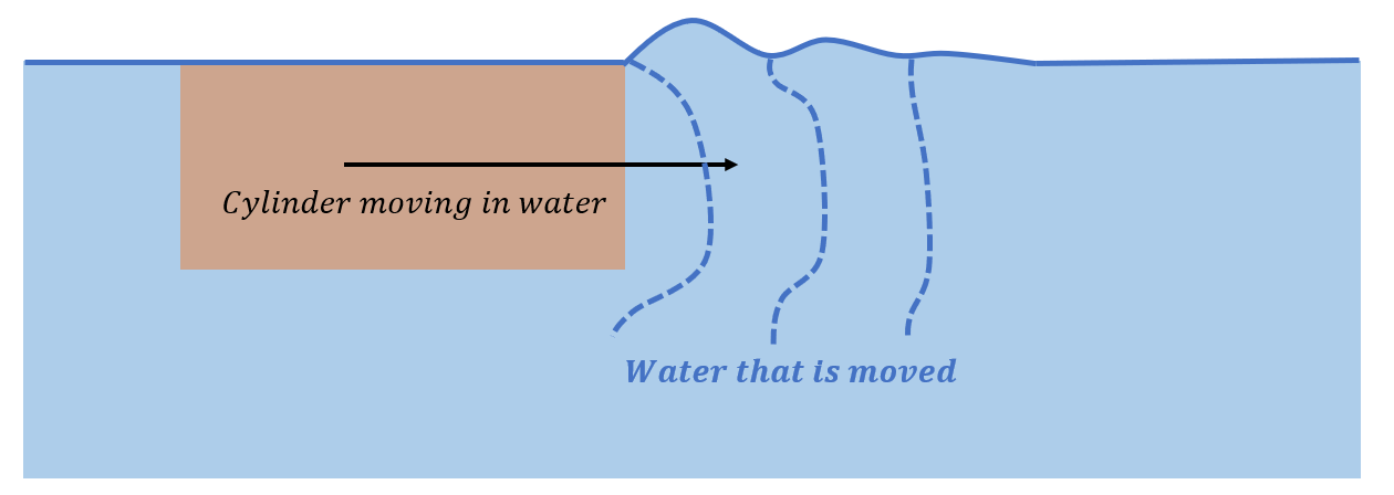
Added mass and damping
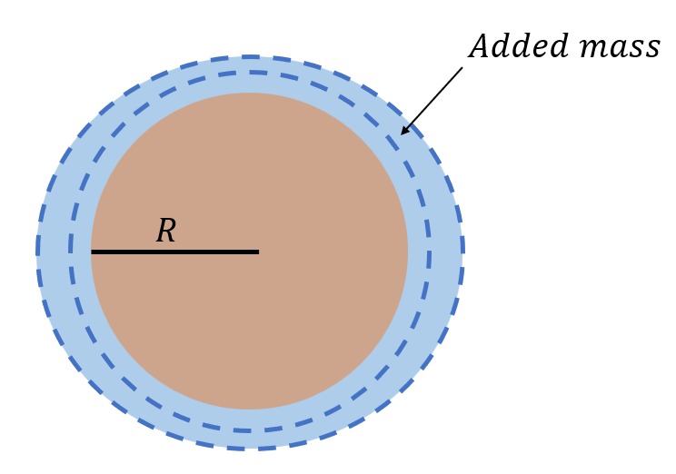
Added mass is an inertia force that arise because water has mass, and this mass resists changes in motion. When a structure accelerates in water, some of this water must also accelerate with the structure, both vertically and horizontally. Damping is the force that resist the relative motion between the structure and surrounding water. This causes the structure to have lower response.
The Added mass coefficient horizontal, Added mass coefficient vertical, Hydrodynamic damping coefficient horizontal and Hydrodynamic damping coefficient vertical should all be set to 0.0. This is because the Flexible tarp model already includes its own internally calculated inertia and damping effects. Adding Morison-type coefficients on top of that will double-count these forces. These parameters should be accounted for when applying MacCamy-Fuchs or Numerical diffraction models.
Damping coefficient (flexible tarp) normal
This is a type of damping that regulates the response of the lice skirt, meaning how much the skirt should follow the fluid particle motion. It is applied locally on each panel, in normal direction. A value of 1.0 corresponds to a condition where the panel motion follows the wave particle motions, implying that there is no relative motion between the panel and the surrounding fluid in normal direction.
In this tutorial, the Damping coefficient (flexible tarp) normal is set to 1.0. This corresponds to applying 100% of the damping that AquaSim calculates.
Please note that this parameter should not be confused by the Hydrodynamic damping coefficient, which represents Morison damping and is not based on relative velocity between the skirt and fluid. The Damping coefficient (flexible tarp) is a built-in damping effect on the lice skirt deformation (or response).
Damping coefficient (flexible tarp) tangential
This parameter also regulates the response of the lice skirt, but tangential to each panel. The Damping coefficient (flexible tarp) tangential is derived from the damping in normal direction. Generally, this damping is considered small compared to the normal direction. For numerical stability of your analysis, you should apply a damping in this direction as well.
This parameter is set to 0.05, meaning 5% of the damping found in normal direction is applied tangential to each membrane panel.
Advanced
The Advanced section provides parameters to modify how environmental loads from waves and current should be applied to the structure. These options allow the user to adjust or refine the hydrodynamic load model beyond the standard methods.
Parameters found here is outside the scope of this tutorial. So, it is not further discussed. More information about this is found in (Aquastructures, 2025b) and (Aquastructures, 2025c).
Sloshing
Sloshing is oscillatory motions of a free surface inside an enclosed volume. Sloshing requires a more or less enclosed volume with rigid boundaries that allow the internal water to oscillate. A lice skirt is open at the bottom, so the water cannot be trapped. So, no standing sloshing mode can be formed in this case study. Therefore, sloshing is not considered in this tutorial.