Case study – Euler beam
Last reviewed version: 2.19Learning objectives
In this case study you will be presented to buckling analysis of a beam that is exposed to a compressive load. The aim is to find the buckling factor. Upon completion of this case study, you will know:
- basics of beam buckling
- basic concepts of critical buckling load and buckling factor
- conduct a buckling analysis in AquaSim.
Introduction
We should investigate buckling of a Euler beam. A Euler beam is a beam which follow the Euler-Bernoulli beam theory.
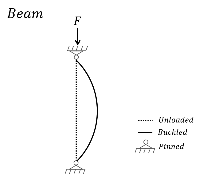
Consider a straight, prismatic beam. The beam is pinned in both ends. When the beam is exposed to compressive load, it deforms until it reaches a point where it becomes unstable, causing the lateral displacement to increase uncontrollably. This instability is known as Euler buckling and occurs when the axial compressive load exceeds a critical value. Note that the theory assumes a linear relation between stress and strain in the material. The critical buckling load P_cr for a beam is described as:
$${ P_{\text{cr}} = \frac{\pi^2 EI}{(KL)^2} }$$
where E is the modulus of elasticity, I is the moment of inertia for the cross section, K is beam effective length factor and L is the effective length of the beam.
The effective length factor K depends on the boundary conditions of the beam; whether it is free-fixed, pinned-pinned, fixed-pinned etc. For example, if the beam that is pinned-pinned, K is equal to 1, while for other boundary conditions K will be different. Euler’s formula provides a theoretical prediction of the critical load at which buckling occurs. When the applied load exceeds the critical load, the beam becomes unstable in the lateral direction and buckling initiates.
The main particular for the beam is presented in the table below. The weight of the beam has been set to zero to be able to compare AquaSim results and calculations easily. The beam is exposed to a compressive load F=10 000N at the top end.
| Parameter | Abbreviation | Value |
|---|---|---|
| Modulus of elasticity [N/m²] | E | 2.1E+11 |
| Euler effective length factor [-] | K | 1.0 |
| Width [m] | W | 1.0 |
| Thickness [m] | T | 0.1 |
| Area moment of inertia [m⁴] | I | 8.33E-05 |
| Weight in air [kg/m] | m | 0.0 |
| Length [m] | L | 10.0 |
| Compressive load [N] | F | 1.0E+04 |
Applying the formula presented in the introduction, the following critical buckling load is calculated:
$${ P_{\text{cr}} = \frac{\pi^2 EI}{(KL)^2} = 1727 , \text{kN} }$$
Buckling analysis of beam modelled with type Morison submerged
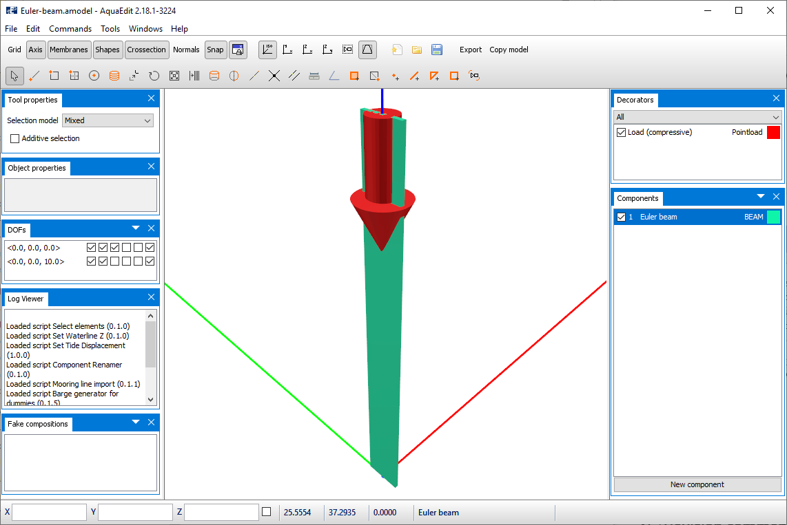
For this case study the beam is modelled with component BEAM and type Morison submerged. You may apply the AquaSim model Euler-beam.amodel that is associated with this tutorial.
Beam buckling should now be calculated explicitly from the buckling analysis tool in AquaSim. The results are then compared with the formula from the previous section.
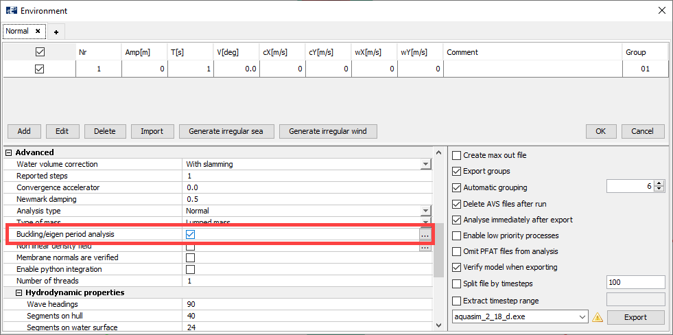
In the AquaSim model, go to the Export menu, and from the Advanced section, select the checkbox Buckling/eigen period analysis.
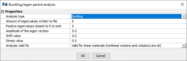
Then select the tree dots […] to the right to enter the control window for buckling analysis settings. Analysis type should be Buckling, Amount of eigenvalues written to file should be 6 and the Amplitude of the eigen vectors can be left equal to 5.
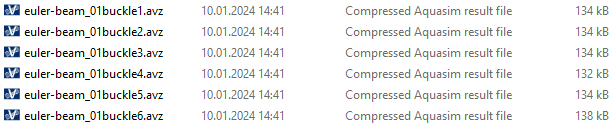
Select OK. Export the model and run the analysis. In this case study we have named this analysis euler-beam_. When the analysis is finished, the files euler-beam_01buckle1 -6 should have been generated. These files contain the buckling factors from the analysis.
Load euler-beam_01buckle1.avz in AquaView. Select Result > Results > Buckling factor. The buckling factor is found to be approximately 172.72.
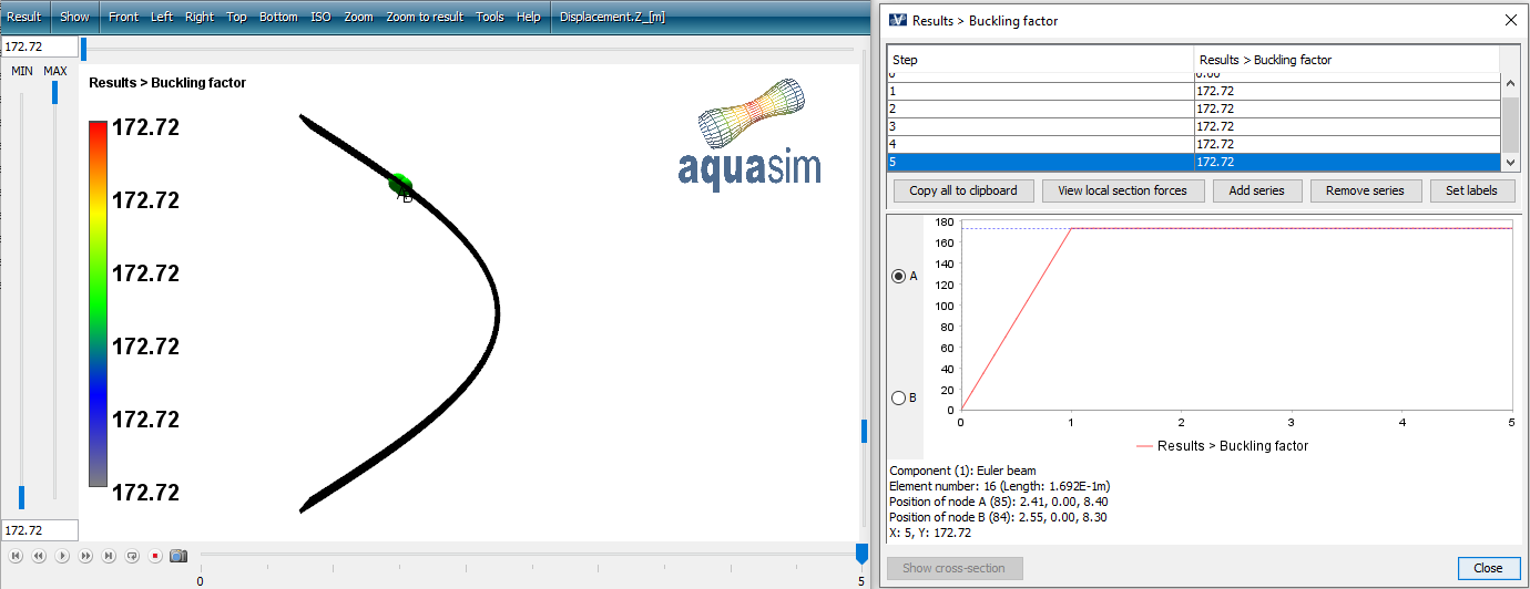
The buckling factor is the critical buckling load \(P_{cr}\) divided by the load in the element:
$${ \text{Buckling factor} = \frac{P_{\text{cr}}}{F} }$$
In this case, the element was subject to a compressive load of 10kN, meaning that the corresponding critical buckling load then will be 1727.2 kN. Comparing this with the calculated Pcr=1727 kN the results compare very well.
Buckling analysis of beam modelled with type Shell
For this case study the beam is modelled with component MEMBRANE X and type Shell. You may apply the AquaSim model Euler-shell.amodel that is associated with this tutorial.
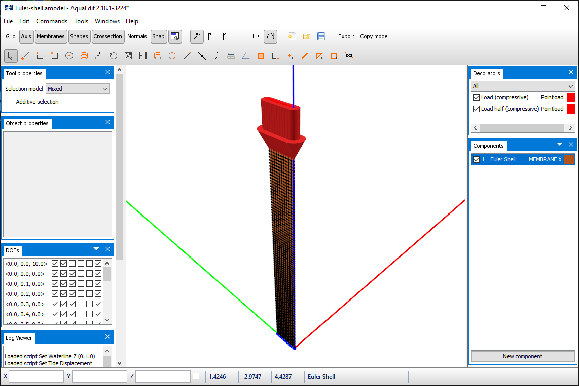
The model is built up with membrane panels of 0.1 x 0.1 m, and the thickness is 0.1 m. This will result in a model with a total of 1000 panels. The boundary conditions at the top and bottom of the model are equivalent as for the beam-model from previous section.
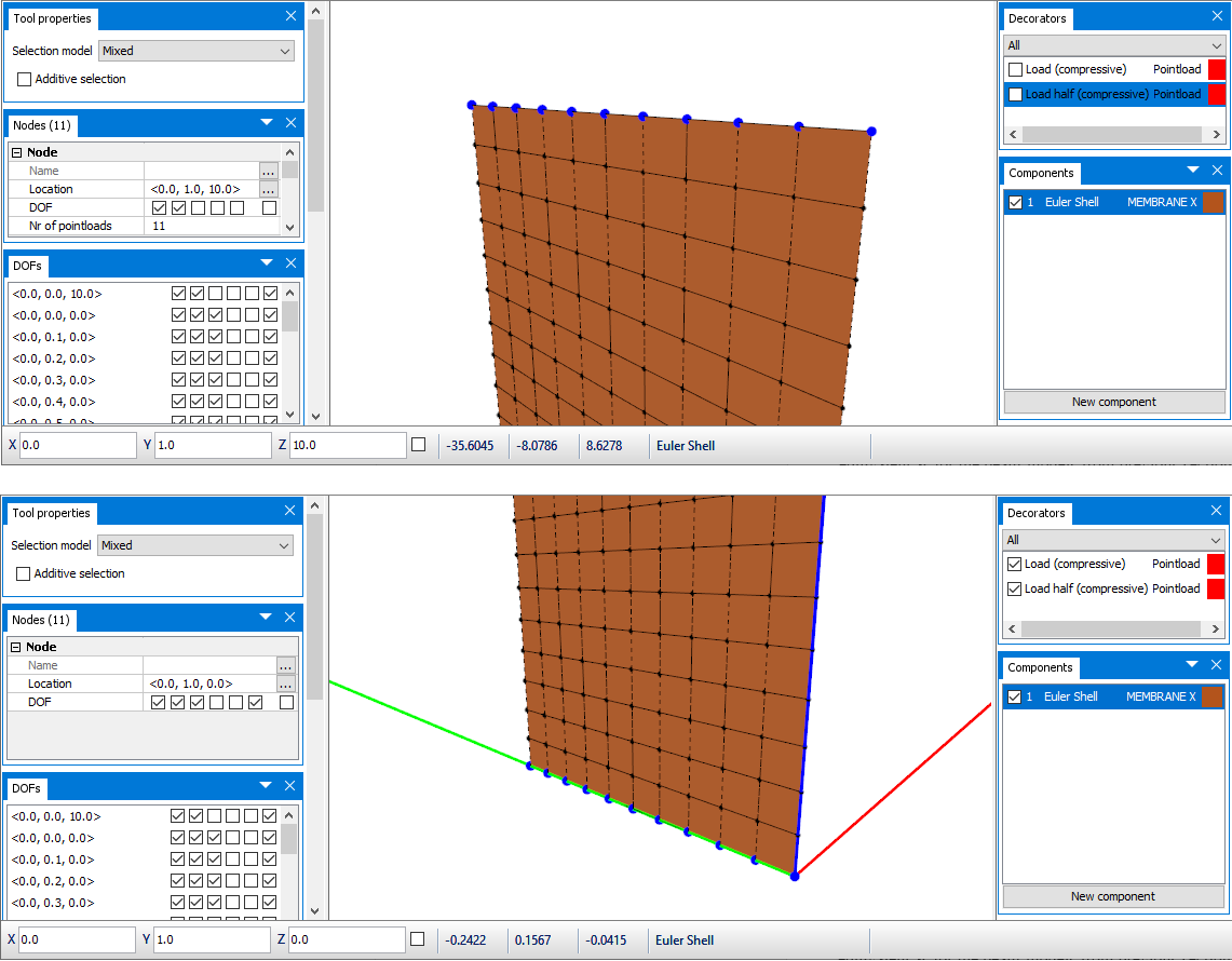
At the top, Pointloads are placed on all 11 nodes. The corner nodes have a load of 500 N each pointing downwards, where the middle nodes have 1000 N pointing downwards. Export your model and run a buckling analysis, the same options as for the beam case is applied for the shell as well. In this case study we have named this analysis euler-shell_.
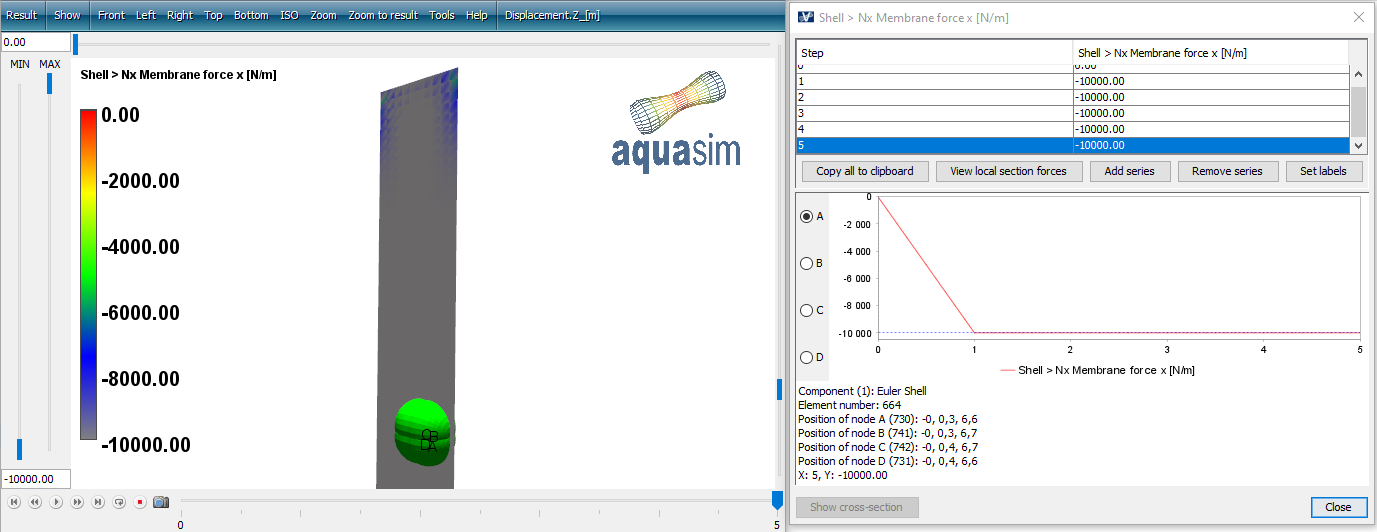
The applied Pointloads in the model will result in an approximate 10 kN through the cross section of the model, apart from some boundary effects at the top and bottom of the model. This is seen as axial force in local x-direction in the figure below, taken from euler-shell_01.avz.
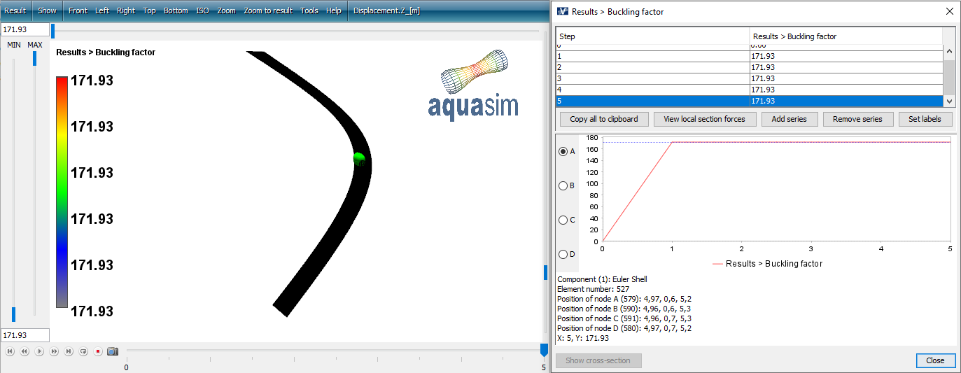
Load the file euler-shell_01buckle1.avz in AquaView. Select Result > Results > Buckling factor. The buckling factor is approximately 171.93. This aligns very well with the results for a beam.
It should be noted that all buckling results in AquaSim is based on the applied element material stiffness matrix and the geometrical stiffness. Euler beams have a stiffness and a geometrical stiffness which is exact relative to the critical buckling load Pcr. Shell elements have a numerical formulation both for element stiffness and geometric stiffness, and results will depend on that.
Buckling analysis of beam modelled with type Normal with bending stiffness
A third version of the beam has been investigated. In this case, the beam is modelled with component MEMBRANE X and type Normal with bending stiffness. You may apply the AquaSim model Euler-normal.amodel that is associated with this tutorial.
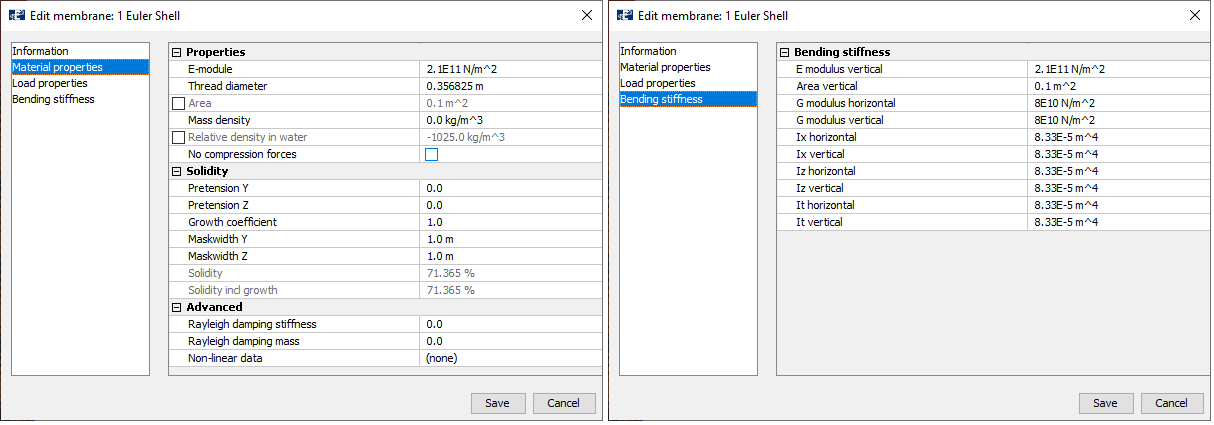
The thread diameter is set such that the cross-sectional area of the panels corresponds to 0.1 m2. Dimensions and material properties are set such that the system is equivalent to the model with beam; Material properties and Bending stiffness is shown below.
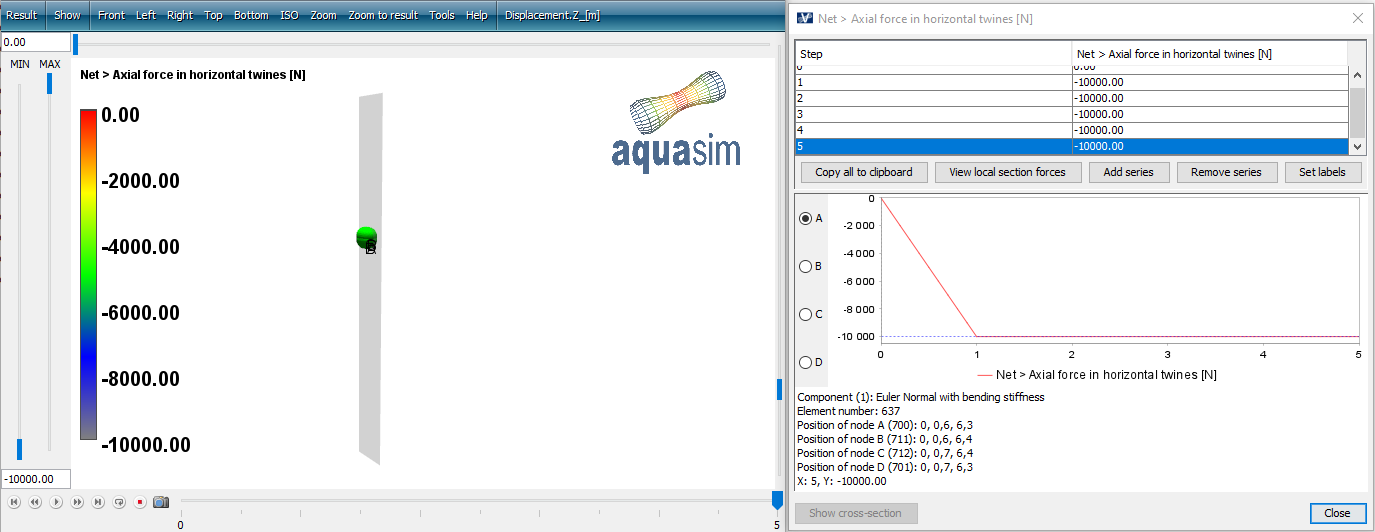
The prepared model can be Exported and run as it is. The analysis is named euler-normal_. In the result file euler-normal_01.avz select Result > Net > Axial force in horizontal twines [N] to view the force through the cross section of the model. It corresponds well with the applied Pointloads from AquaEdit.
The buckling factor is reported in euler-normal_01buckle1.avz, and is found to be around 172.65. If we multiply this with the compressive load that is applied to the model, we see that also this model correspond well with the calculation of Pcr=1727 kN.

Summary
In this tutorial you have been introduced to buckling analysis in AquaSim. Buckling analyses can be performed on selected component types. AquaSim account for geometric instabilities.