Wave period consideration in added mass and damping
Last reviewed version: 2.22Introduction
The purpose of this tutorial is to provide an introduction for how to adjust the wave period for the numerical calculation of added mass and hydrodynamic damping in AquaSim for analyses with irregular waves As outlined in (Aquastructures AS, 2025a), the mean zero crossing period of the wave spectrum (Tz) is used as basis for the calculation of added mass and hydrodynamic damping, when irregular waves are considered, assuming that the parameter “Enable convolution integral” is untoggled, as seen in Figure 1 for “Beam” and Figure 2 for “Membrane/Membrane X”.
This is the case both for element type “Beam”, when using load formulation “Hydrodynamic” and for element type “Membrane/Membrane X” when using load formulation “Lice skirt” or “Closed compartment” along with “Numerical diffraction”.
In AquaSim one may calculate hydrodynamic properties, i.e. added mass and hydrodynamic damping, for irregular waves in AquaSim, using a period (T) that differs from the mean zero crossing period of the wave spectrum (Tz).
In certain cases, one may prefer to use the wave spectrum’s peak period Tp, or alternatively a natural period Tn (corresponding to a certain degree of freedom or eigenmode of the system), depending on whether the system response is force-driven or resonance-driven. Additionally, for double-peaked wave spectra (with both wind-generated waves and swell), this allows selecting which of the peaks’ Tp to use in the calculations.
This document provides a step-by-step description of how this can be achieved in AquaSim.
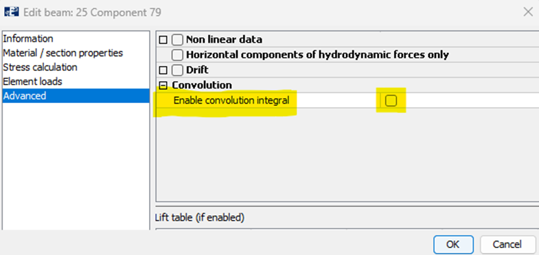
Figure 1 How to enable forces caused by convolution for hydrodynamic response, for element type “Beam” using load formulation “Hydrodynamic”.
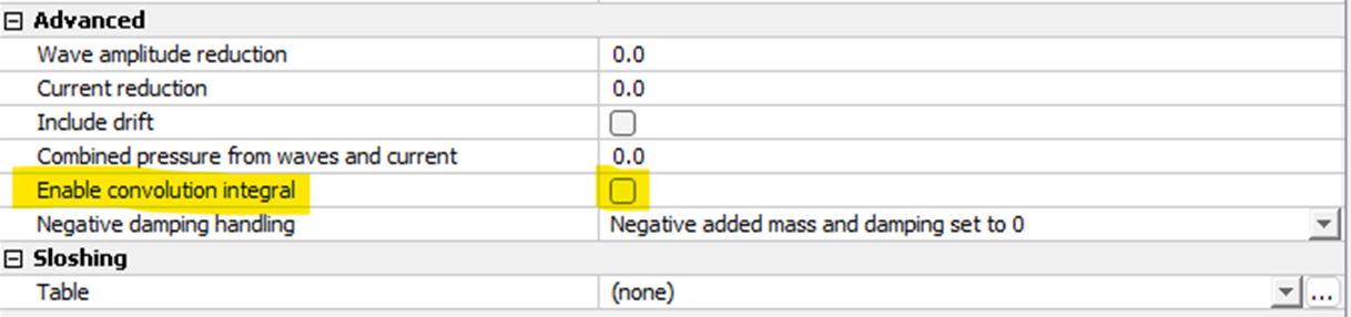
Figure 2 How to enable forces caused by convolution for hydrodynamic response element type “Membrane/Membrane X” when using load formulation “Lice skirt” / “Closed compartment” along with “Numerical diffraction”.
Step-by-step tutorial
Step 1: Generate irregular waves
The first step is to go to the Export-window in AquaEdit, to generate an irregular sea-state from the significant wave height (Hs), wave period (Tz), total number of steps for waves and number of steps per wave, as shown in Figure 3 - Figure 5.
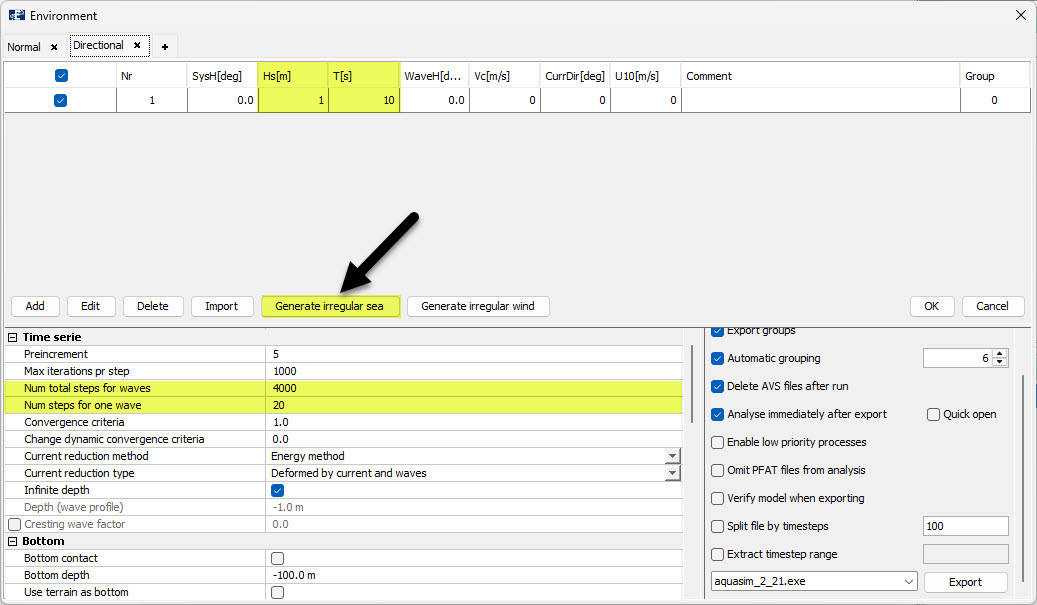
Figure 3 Generating irregular waves in AquaSim in the Export-window.
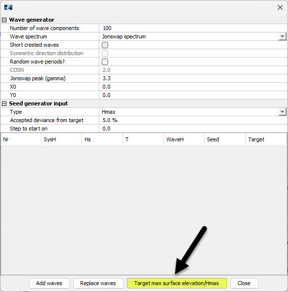
Figure 4 Generating irregular waves in AquaSim in the Export-window, after pressing “Generate irregular sea”.
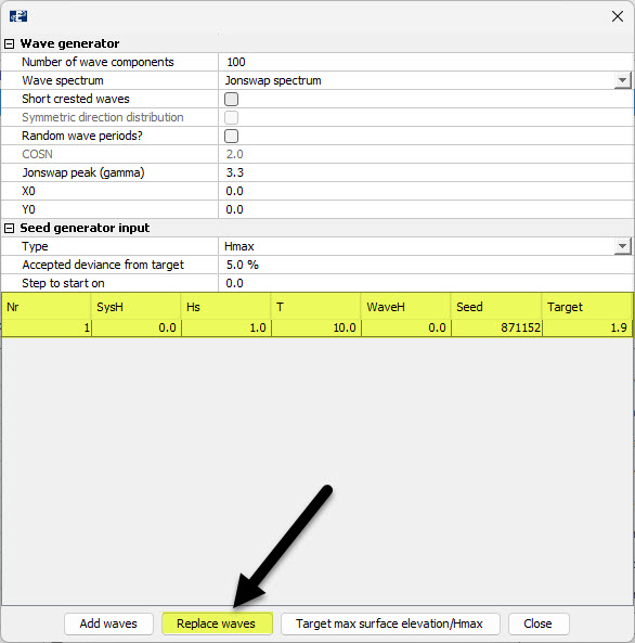
Figure 5 Generating irregular waves in AquaSim in the Export-window, after pressing “Target max surface elevation/Hmax”.
Step 2: Verify spectrum after generation of irregular waves
After generating the irregular waves, you will see in the Export-window in AquaEdit that you get a darker background for significant wave height (Hs), wave period (Tz), indicating that you have generated an irregular sea-state, as shown in Figure 6.
Thereafter, when pressing Edit you will see that the mean zero crossing period of the wave spectrum \(T_Z=10.0s\), as shown in Figure 7. Furthermore, when you plot the wave spectrum you will see thatsee the peak period of the wave spectrum \(T_P≈12.0s\), as shown in Figure 8. For Jonswap spectra \(T_P≈1.2*T_Z\).
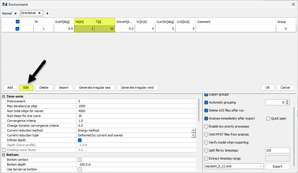
Figure 6 Export-window, after generating irregular waves.
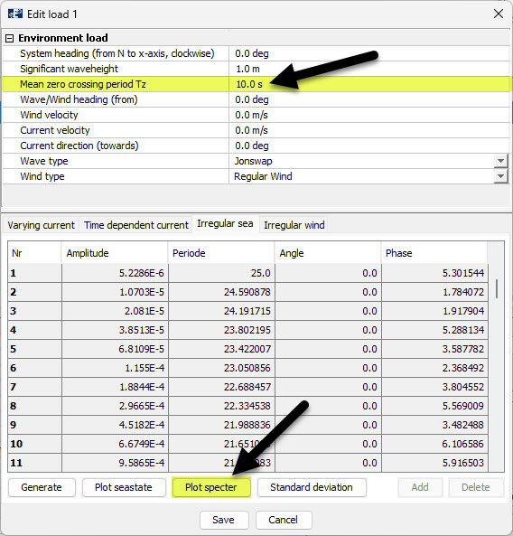
Figure 7 Load condition parameters, after generating irregular waves.
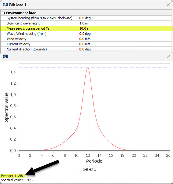
Figure 8 Tp and Tz of wave spectrum that has been generated.
Step 3: Edit load condition of irregular waves
After generating the irregular waves and verifying the wave spectrum, you can then press Edit once again and change the value of the mean zero crossing period of the wave spectrum (Tz) to your desired value. In this case, we set \(T_Z=5.0s\) and press “Save”, as shown in Figure 9. AquaSim will now use a period of T=5.0s, when numerically calculating the added mass and hydrodynamic damping.
After having done this, you will see that when you plot the wave spectrum again, that it remains unchanged and in addition you will see in the Export-window that T=5s, as shown in Figure 10.
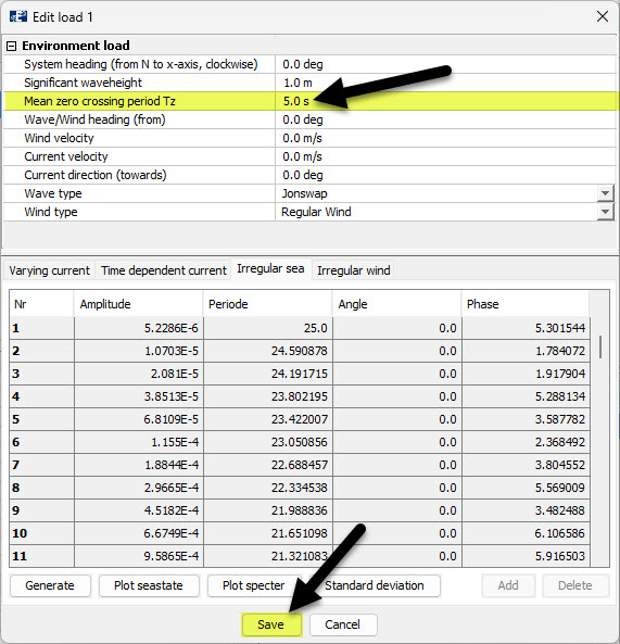
Figure 9 Changing Tz in the load condition parameters, after having generated irregular waves.
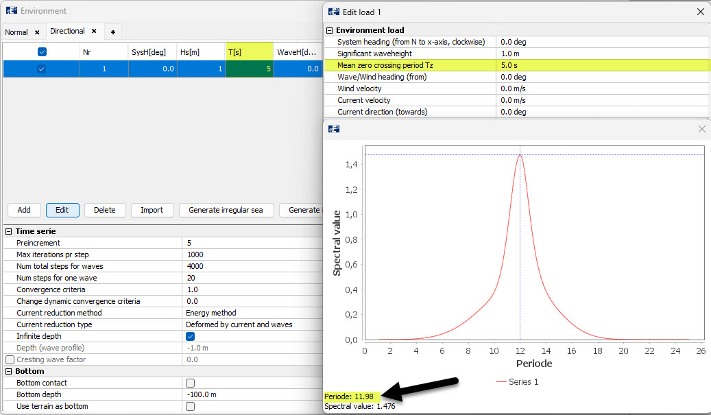
Figure 10 Export-window and wave spectrum after changing Tz in the load condition parameters, after having generated irregular waves.
Alternatively, you may also change the wave period directly in the Export-window after having generated the irregular waves, as shown in Figure 11.
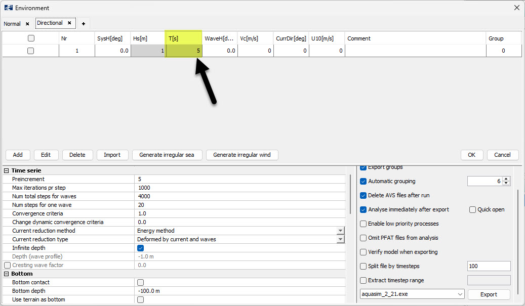
Figure 11 Edit wave period directly in Export-window, after having generated irregular waves.
References
Aquastructures AS. (2025a). On numerical calculation of diffraction forces, added mass and hydrodynamic damping. TN-FOU-101830-1. Revision 1.