Pre processing
Last reviewed version: 2.18.0Establish outline for hexagonal masks
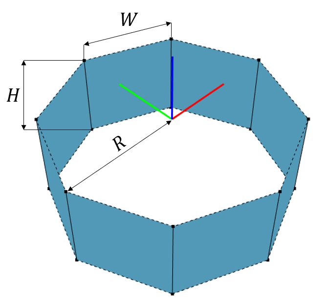
Load AquaEdit and create an outline with 8 sides and dimensions as described below. The outline should be of the component type MEMBRANE X, and the centre should be situated in the global origin (x, y, z) = (0, 0, 0).
| Dimensions of outline | |
|---|---|
| Radius (R) | 26.131 m |
| Width (W) | 20 m |
| Height (H) | 20 m |
Tip! How to generate the 8-sided outline: Start with a component type TRUSS and generate a circle with 8 segments and radius equal to 26.131m.
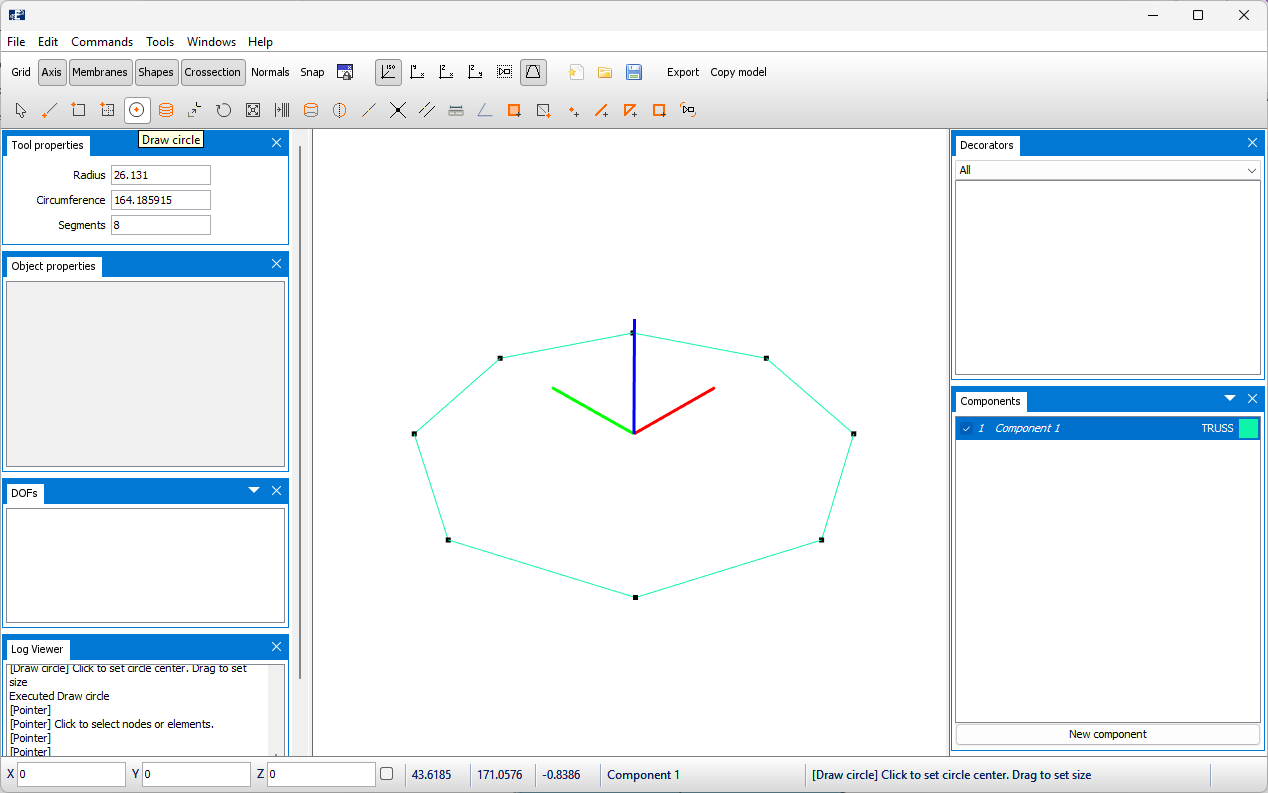
Extrude path 20m in negative z-direction.
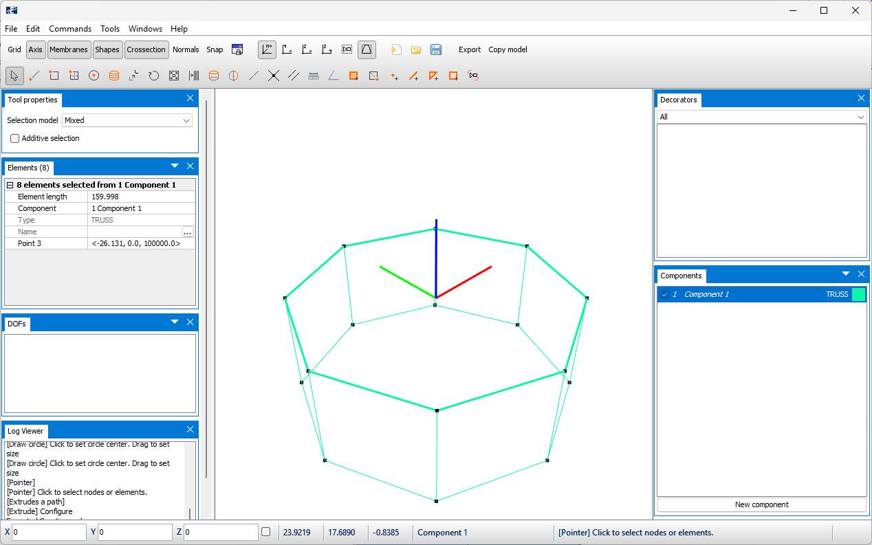
Then change the component type from TRUSS to MEMBRANE, then to MEMBRANE X
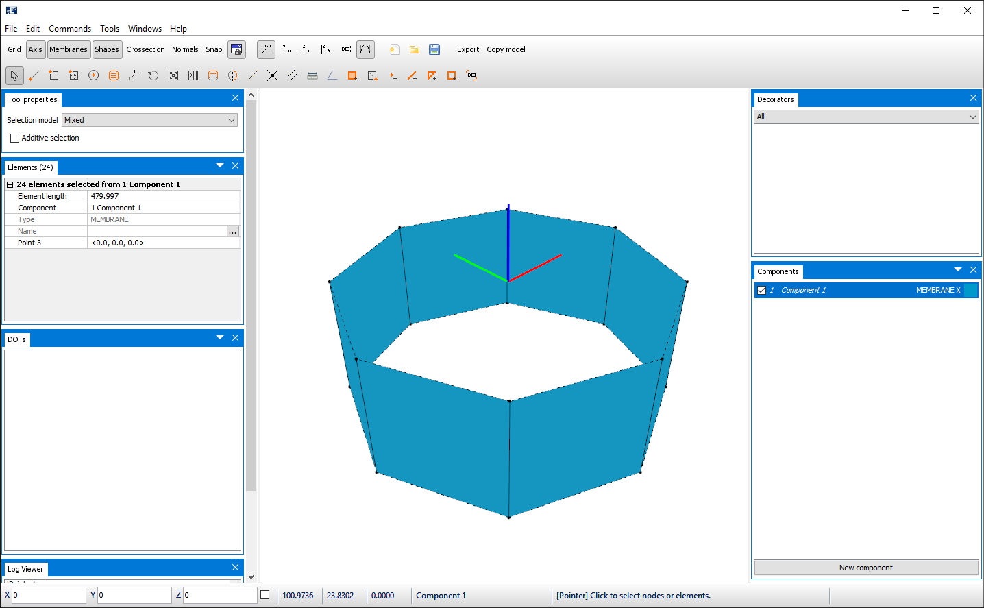
When generating the outline, it is advised that the horizontal elements are as parallel as possible and of equal lengths. This also apply for the vertical elements.
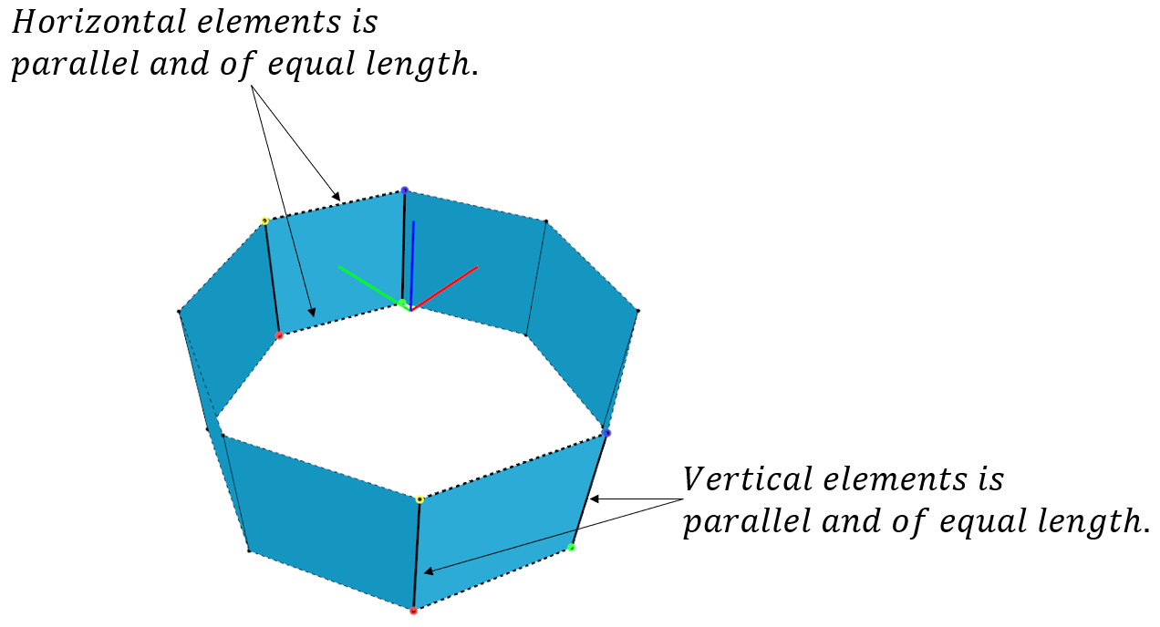
This is recommended in order to ensure that the masks will coincide between the side surfaces. An example of what is meant by coincidence of the masks and not is illustrated in the figure below.

Generate Hex: Sides
In this section, masks on the container sides should be generated. The parts that should be included to generate the masks should be selected. To select MEMBRANE X components, select Pointer and from the drop-down menu choose Quads.

Box-select the outline from the 3D window.

Each corner of the nodes is assigned a colour. Red to green is the first horizontal edge, green to blue is the first vertical edge. Blue to yellow is the second horizontal edge, and yellow to red is the second vertical edge. This is important: the horizontal and vertical lines indicate the direction of the masks.
Go to Tools > Generate Hex and select the tab Membrane.

Input parameters for the mask should be:
- Knot length = 100 mm
- Mask height = 200 mm
- Mask width = 400 mm
- Thread diameter = 20 mm
Emit connectors: connectors are truss elements modelled between the edges of the outline. By toggle on, these truss elements are included when generating the masks. We want to include the trusses and leave this option activated.
Scale: scale the mask size. This option is dependent on the Fit, so if one adjusts one the other option is updated. We do not make any changes here.
Axis length: indicates the length of the edge between the red to green node. That is, the horizontal line.
Fit: this is the number of masks that should be generated from the red to green node (horizontal edge). We choose to have 5 masks fitted in the outline, so we type Fit = 5.
Select Generate membranes. When the masks are generated, you can select Close in the Generate Hex window. The model should now resemble the figure below.
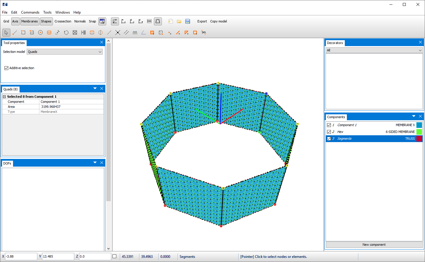
In the Components window you will see that two new component groups are generated: Hex and Segments. Hex is the hexagonal masks and is assigned to the component type 6-SIDED MEMBRANE. Segments is generated due to activating the Emit connectors in the Generate Hex, tool and is component type TRUSS.
Generate Hex: bottom
In this section, masks on the container bottom should be generated. The tool Generate Hex provide a tab for generating this. Go to Tools > Generate Hex and select the tab Bottom.
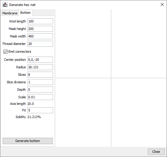
The bottom-masks should have the same properties as the side-masks, we type:
- Knot length = 100 mm
- Mask height = 200 mm
- Mask width = 400 mm
- Thread diameter = 20 mm
Center position: is the coordinates of the centre point for the bottom. The height of the outline was 20 meters; hence we type 0, 0, -20.
Radius: this is the radius of the bottom, measured from Center position. For the bottom to coincide with the lower edge of the sides, the radius should equal the distance from Center position to the lower edge of the sides. From before we know this is 26.131 meters.
Slice: is the number of divisions of the bottom. By default, this is 8. In our case we have a total of 8 sides, hence we type Slice = 8.
Slice division: the number of Slices may be further subdivided with the use of Slice division. Applying e.g., 2 will result in a total of 16 slices when Slice = 8. We only want to have a total of 8 slices, hence: Slice division = 1.
Tip!
The effect of Slice division: To illustrate the Slice division, the figure below presents how the bottom would be if Slice=8 and Slice division=1.
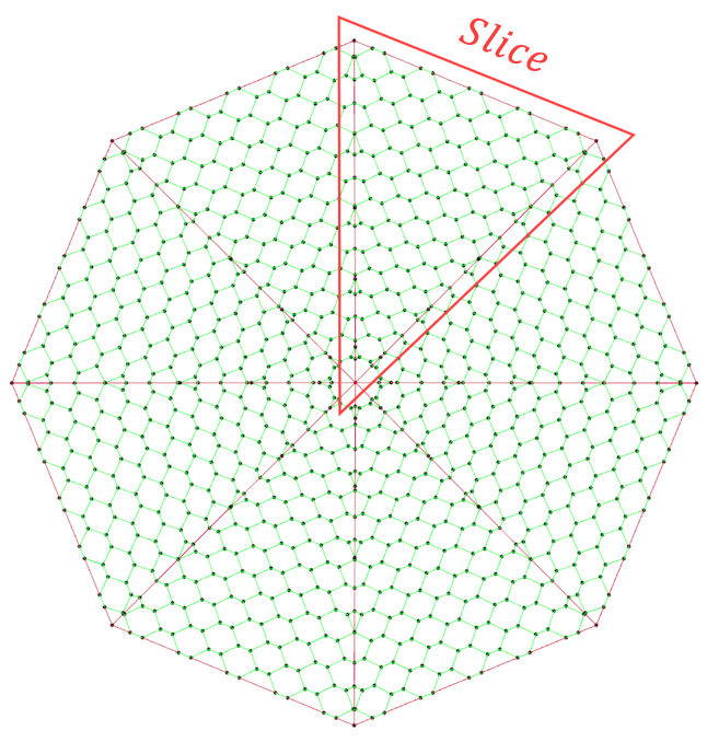
When Slice=8 and Slice division=2.
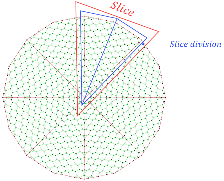
When Slice=4 and Slice division=2.
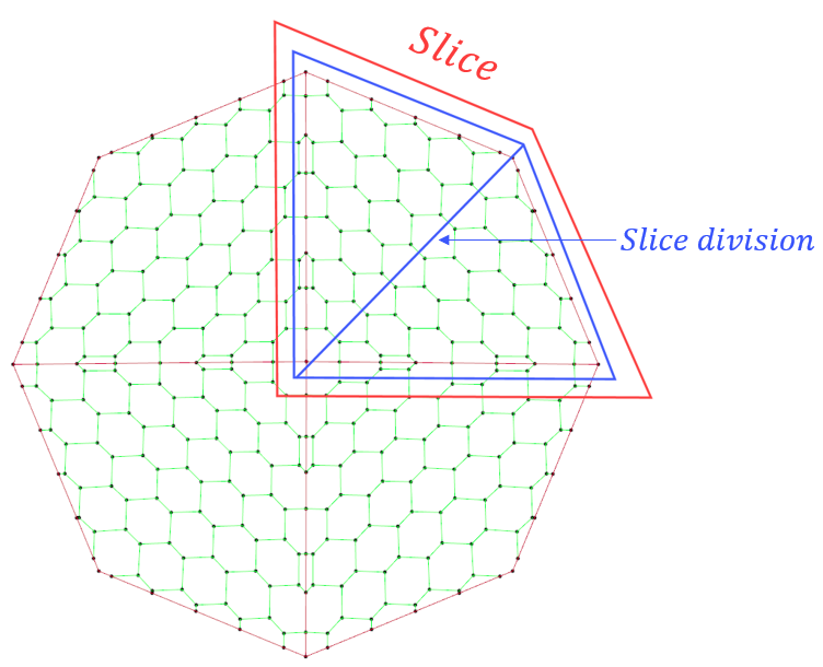
Depth: is the depth of the bottom. The depth is calculated with respect to the vertical position specified in Center position. The unit is meters and is measured downwards, meaning that positive values will create a bottom that has a depth in negative z-direction. Our container should have a depth of 10 meters, hence: Depth = 10.
Scale: scale the mask size. This option is dependent on the Fit, so if one adjusts one the other option is updated. We do not make any changes here.
Fit: this is the number of masks that should be generated from the red to green node (horizontal edge). We choose to have 5 masks fitted in the outline, so we type Fit = 5.
Now, select Generate bottom. When the masks are generated, you can Close the Generate Hex window. The model should resemble the figure below.
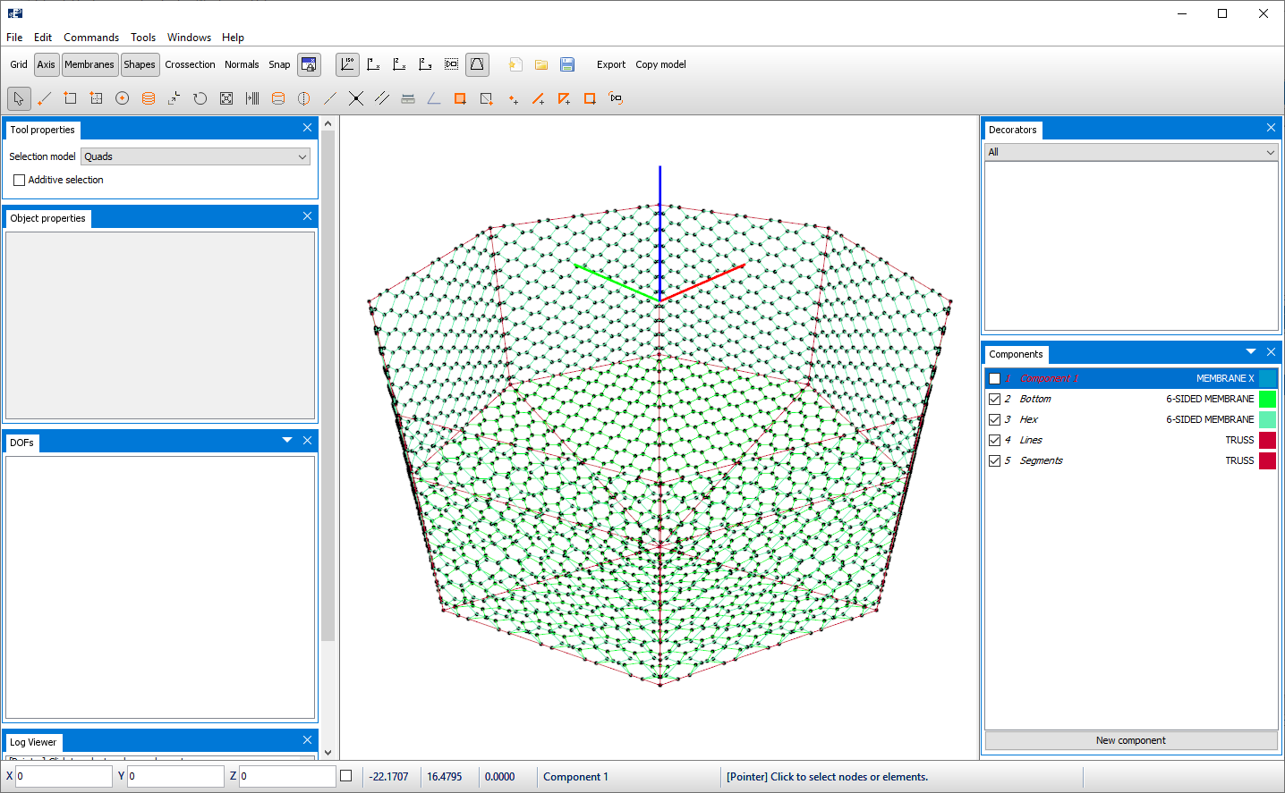
Two new components should have been generated: Bottom and Lines. Now as the masks are successfully generated, you may delete or deactivate the MEMBRANE X component that were applied as an outline because it is of no use anymore.
Boundary conditions
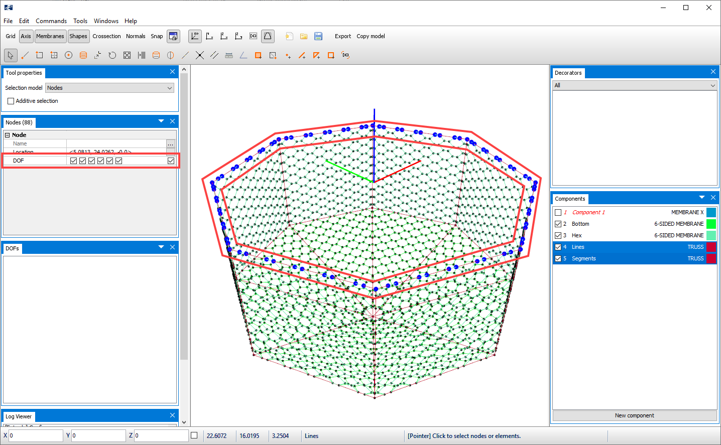
The model needs some boundary conditions, and in this case study we choose to restrain the top nodes of the container in all Degrees of freedom. Select all the top nodes and select the checkbox to the left in the Nodes window.
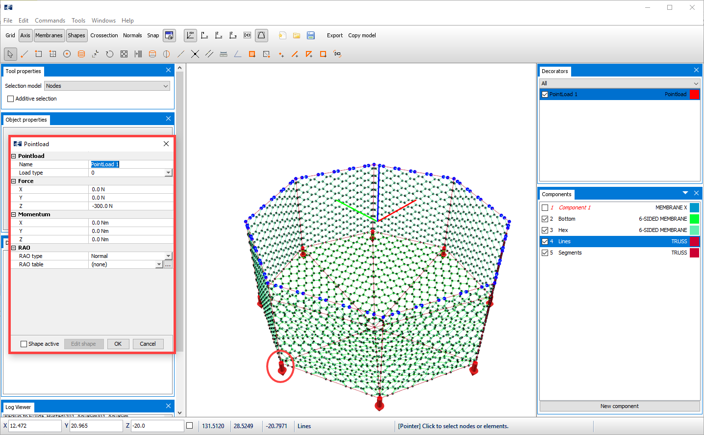
Pointload
To suspend the container sides, we add some Pointloads of -300N in z-direction.
Properties of hexagonal masks
We should give the component groups Hex and Bottom cross-sectional properties. In the components window, double click Bottom to open the Edit Membrane window. The available Type and Load formulation for 6-SIDED MEMBRANE is Normal. Go to the Material properties tab, and insert Thread diameter = 0.02 m, this corresponds to the thread diameter of the Knot.
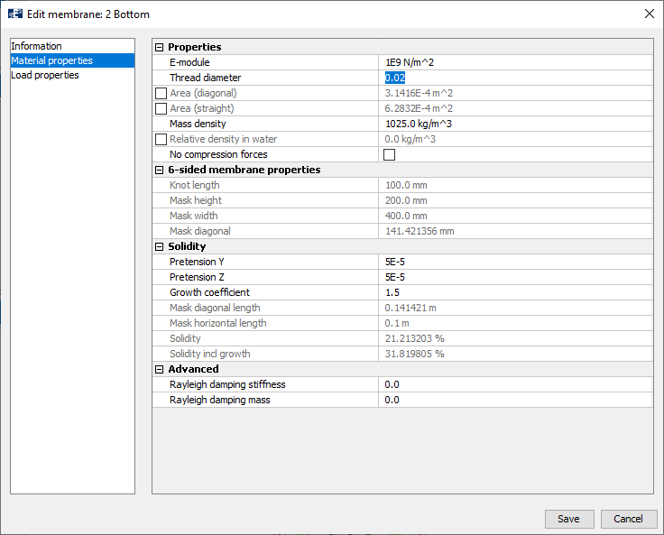
We are satisfied with the parameters and select Save.
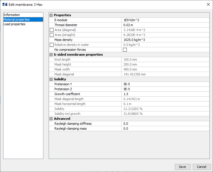
Enter the Edit membrane window for the component Hex and go to the Material properties tab and make sure that the parameters correspond to the figure below. The select Save.
Properties of Segments and Lines
The truss components Segments and Lines are assigned cross sectional properties corresponding to the table below.
| Segments and Lines | |
|---|---|
| E-modulus | 2.1E9 N/m2 |
| Area | 3.8E-4 m2 |
| Weight in air | 0.48 kg/m |
| Diameter Y / Z | 0.022 / 0.022 m |
| Drag coefficient Y /Z | 1.2 / 1.2 |
| Added mass coefficient Y /Z | 1.0 / 1.0 |
Verify the model
To check that the model is correct and without errors, you should check the model through Commands > Verify model.
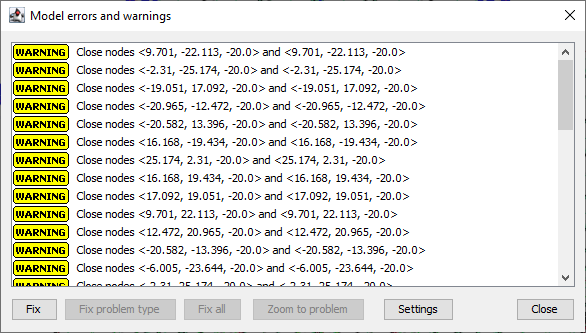
You might, depending on your settings, get a warning for close nodes. Then you should check if there are some nodes that should have been merged.
