Case study – Pre-made turbine
Last reviewed version: 2.19Pre-processing
To establish a turbine, an automatic generator may be utilized in AquaEdit. To do so, you need to generate it on an existing element from the 3D window. Therefore, start with generating what we call the Tower. This is a vertical element, a vertical element and be can e.g. a beam component. The Tower supports the turbine structure and is component connecting the turbine with the foundation.
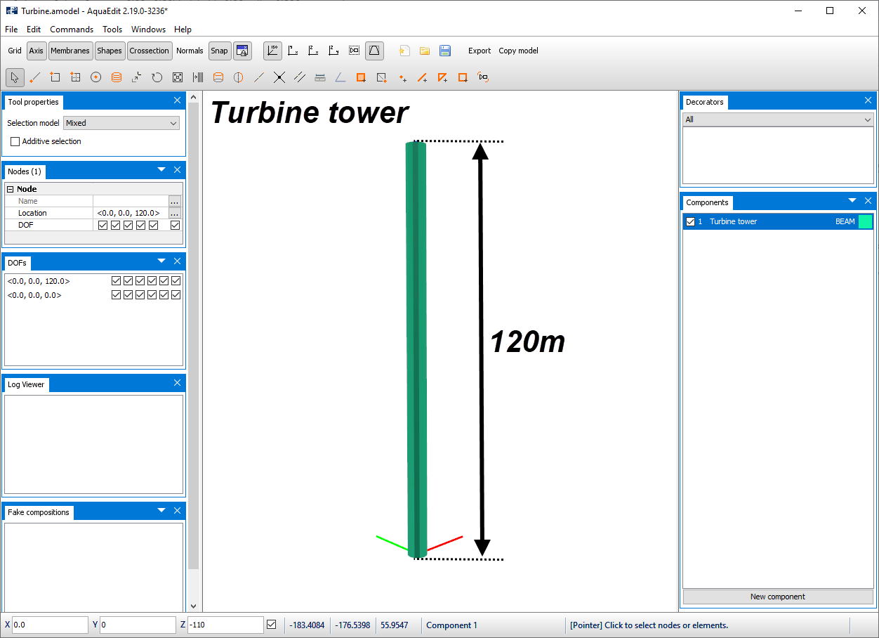
The beam has a diameter of 6.0 meters and is generated from the Data source type Tube in the Edit beam window. The beam is 120 meter in height and is modelled from z=0m.
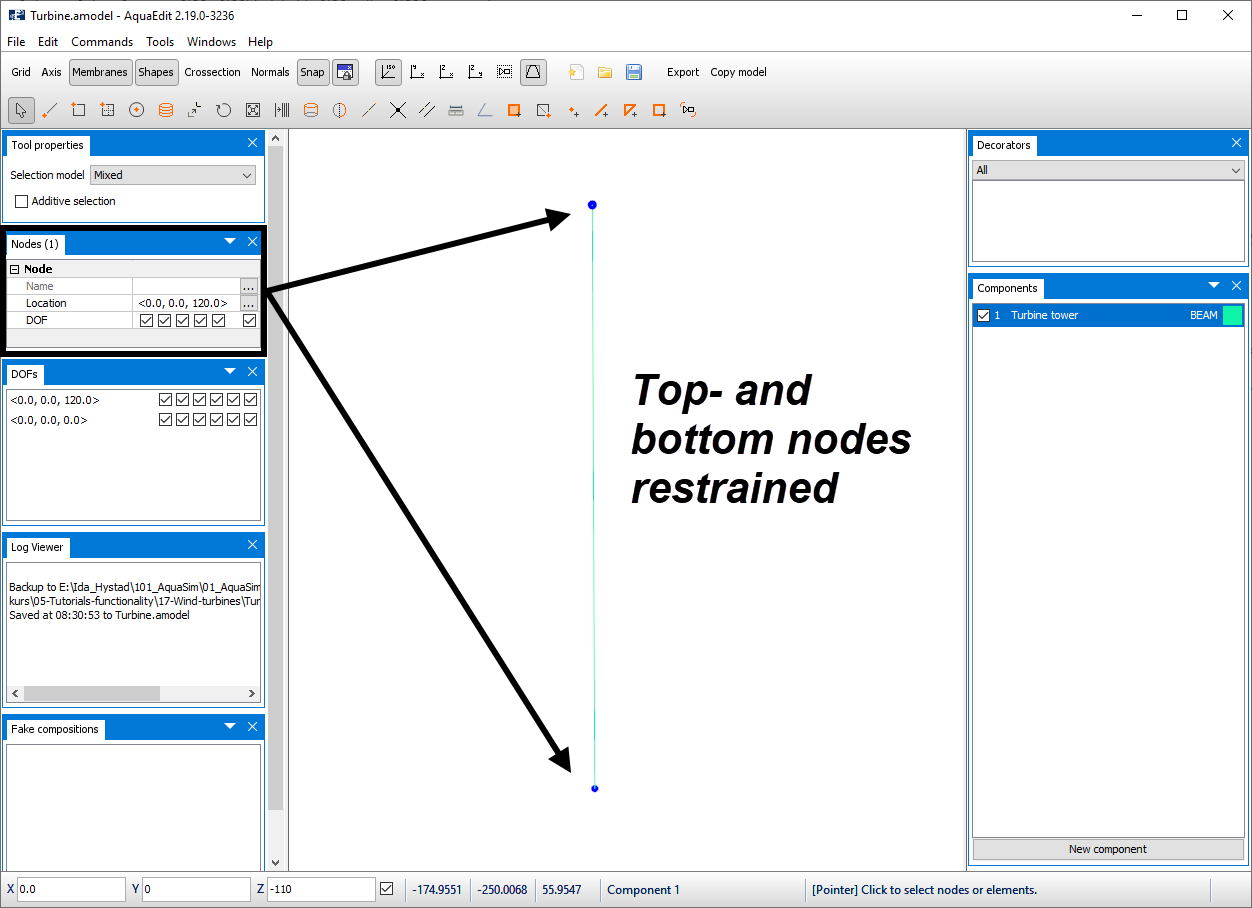
Since we in this section only are interested in basics of the turbine input, the two nodes representing the beam is restrained in all degrees of freedom.
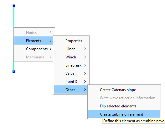
Click on the beam element in the 3D window and select Elements > Other > Create turbine element.
The interface of the built-in Generate turbine-tool will be loaded.
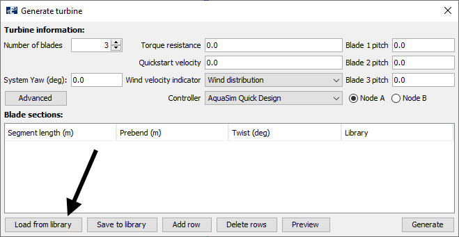
this window, there is currently no turbine generated. This is seen as the Blade sections-area is empty. Turbines can be introduced manually or imported from a file. Once a ‘new’ turbine is built, this can be exported to the AquaSim library. In this way, generating will be a one-time-event.
To import an existing turbine, click on Load from library in the lower left corner of the window. In the file catalogue Library > turbine should be opened as seen in the figure below.
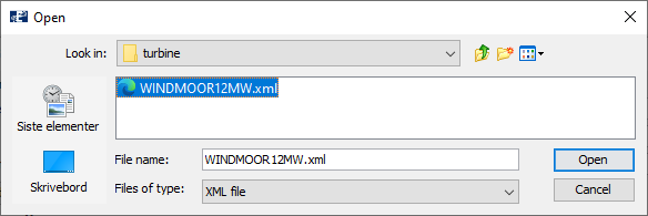
The turbine-folder contain the WINDMOOR12MW.xml turbine, which is included as an example when installing AquaSim. Select Open to load the file into AquaEdit. Then data will be loaded to the Generate turbine-tool, as shown below.
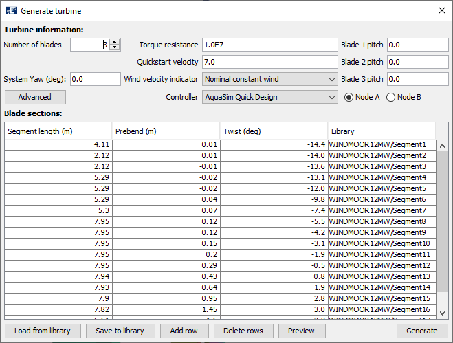
Please note: the WINDMOOR12MW.xml-file from the turbine-folder, is a file that points to the beam library where you find a folder with the same name. This folder contains several xml-files which contain the cross-sectional properties of each blade segment and turbine nave. This you should have in mind when saving properties to library.
Generate turbine-tool
The different options from the top-lines in the Generate turbine-tool are:
-
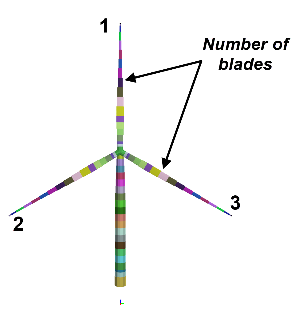
Number of blades [-]: the number of turbine blades that is distributed around the nave. Usually, three blades are applied.
-
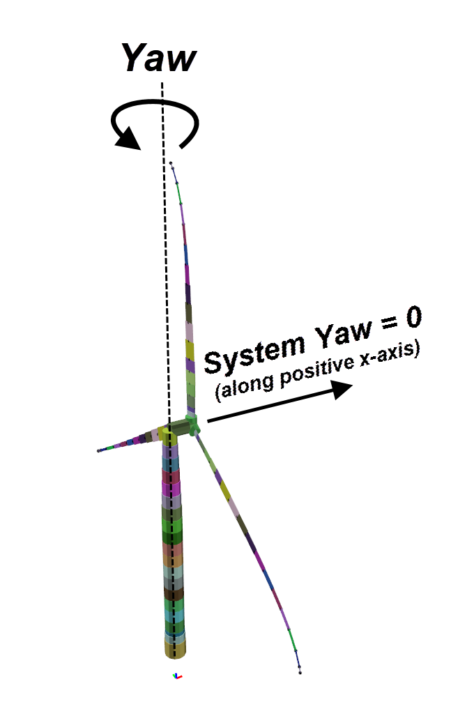
System Yaw [deg]: orientation of the nave and system at the start of the analysis. 0 degrees means that the nave is pointing along the positive x-axis. 90 degrees mean the nave is pointing along the positive y-axis.
-
Torque resistance [Nm/(rad/s)]: this is a resistance that is proportional with the rotational velocity of the nave. This parameter interacts with the controller.
-
Quick start velocity [RPM]: velocity chosen for quick start in the analysis. When the dynamic part of the AquaSim analysis starts, the turbine blades will have this rotational velocity.
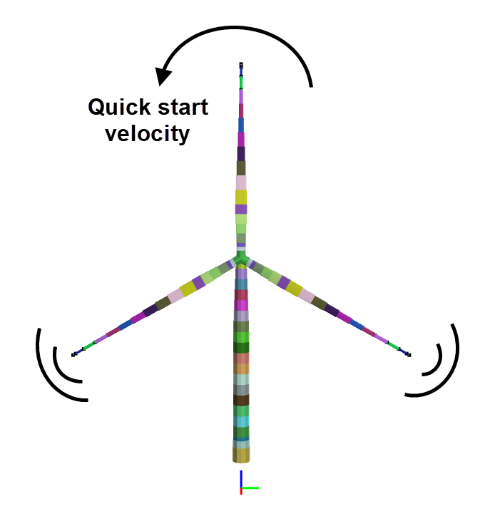
Leave this equal to + 7.0. -
Wind velocity indicator [-]:
- Wind distribution: wind flow predicted by wind distribution (i.e. a wind profile).
- Nominal constant wind: wind flow is flat (constant) fixed wind speed.
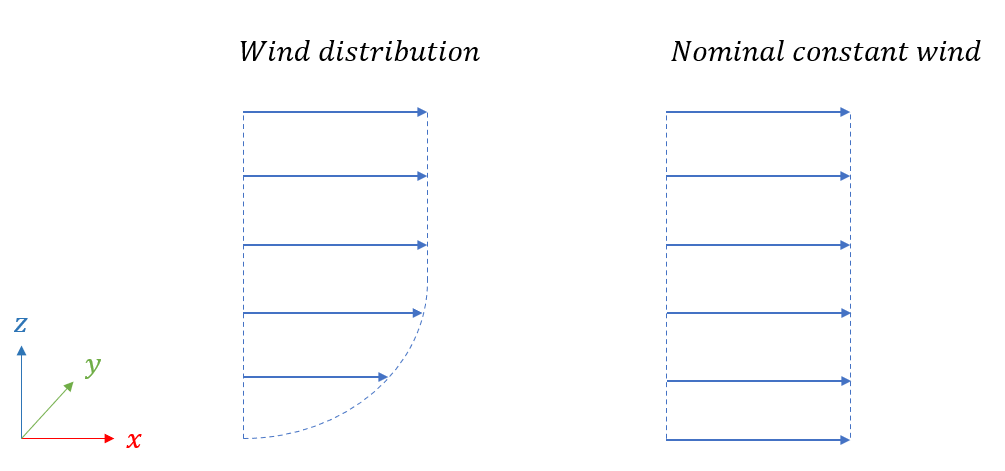
We choose to apply the Nominal constant wind in our case study.
-
Controller: the type of controller that should be applied. The controller regulates the torque resistance, system yaw and blade pitch as the blades rotate. Three options are available:
- AquaSim Quick Design
- Internal
- ROSCO (Python integration)
We choose to apply the AquaSim Quick Design in our case study.
-
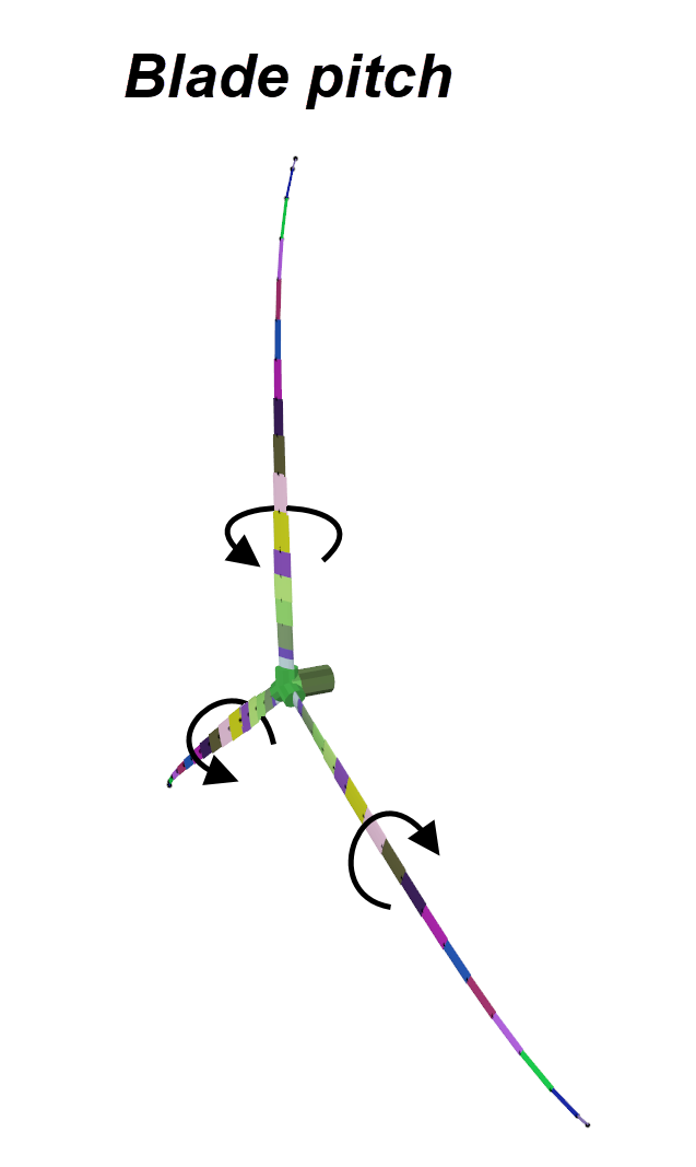
Blade 1-3 pitch: regulates the pitch of the blades.
-
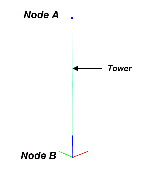
Node A / Node B: which node on the Tower the turbine should be attached to. Node A is the first node that was defined when the Tower-element was drawn in the 3D window. Node B is then the second.
-
Advanced: gives you access to advanced settings for the wind turbine. You can read more detailed information about this in the AquaEdit User Manual (link), or the report TR-FOU-100004-5(link).

Each blade is divided into sections, and for each section the following information is given in Blade sections:
-
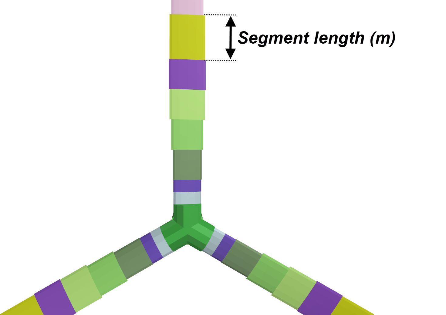
Segment length (m): radial length of each blade segment, in meters.
-
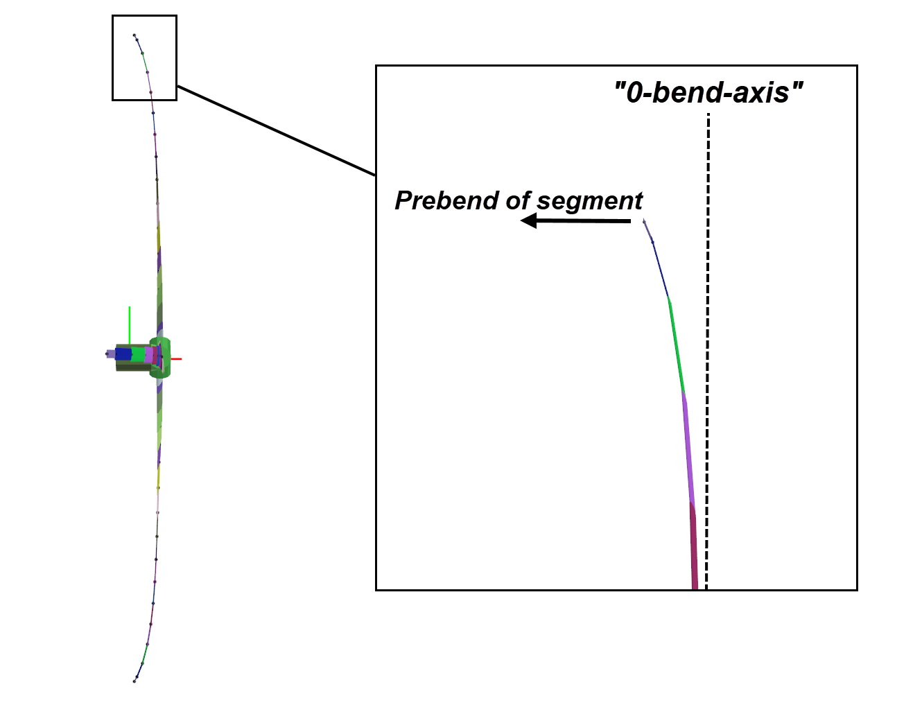
Prebend (m): how much the element is directed towards the wind (if positive values) over the element length. That is, how much more upwards to the wind the outer node of the segment is relative to the inner node.
-
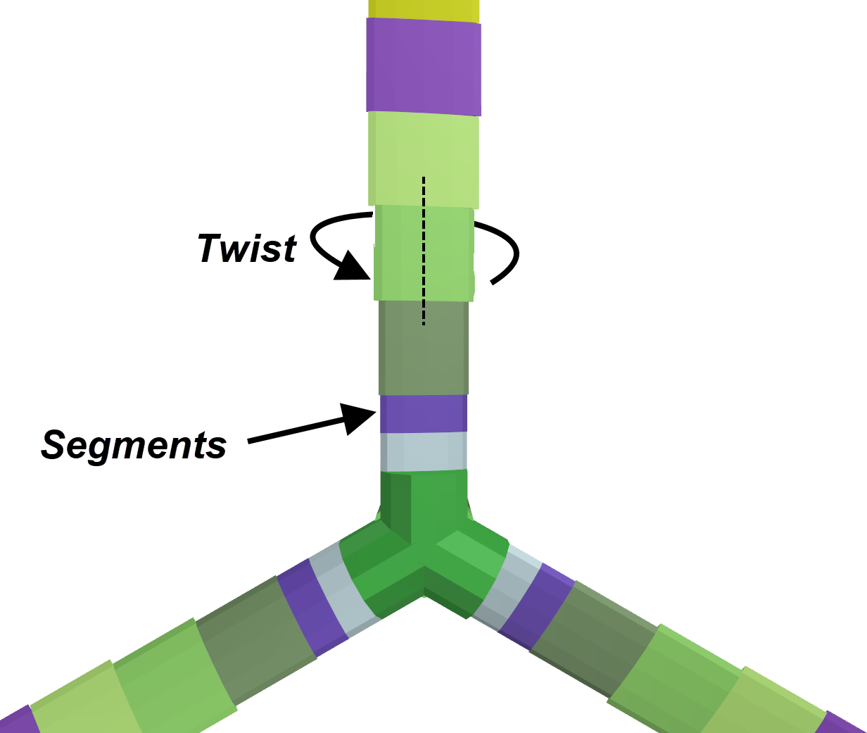
Twist (deg): twist of each segment. This can be viewed as local pitch of each segment in the blade.
-
Library: the path to where the cross-section properties to each segment is located. This coded to point to AquaSim\Library\beam-folder.
The lower part of the window gives you the options to load a turbine from the library or save to the library. The Add row and Delete rows regulates the number of rows in the Blade sections-part of this window. Selecting Preview gives you the option of seeing the turbine without generating it. This is useful in cases where you want to check certain parameters in this window. Generate, generates the turbine. Elements and components needed for the turbine will be generated in AquaEdit.

Let us generate this turbine by selecting Generate.
Turbine components
Your model should now resemble the figure below, where you have a full turbine with shaft, nave and turbine blades.
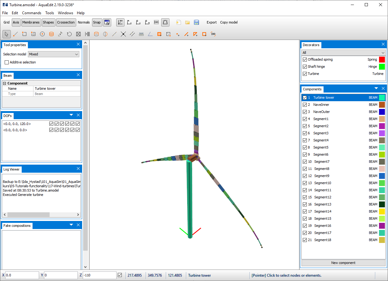
For the WINDMOOR12MW, a total of 18 blade Segments are generated. They are automatically modelled as Beam components and are found in the Components- window. The nave is connecting the Tower to the turbine blades. Node decorators representing the generator, and more is also added.
Blade segments
Double click on one of the segments from the Components-window to view its properties. We have selected Segment3.
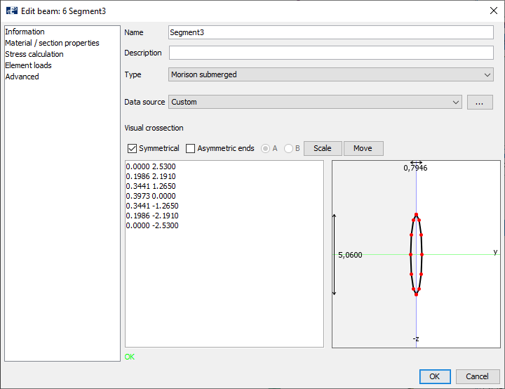
The cross section of the blade is presented in the Information-tab. As default, the beam type is Morison submerged. Meaning forces are calculated based on Morison equation.
Select Advanced to view tables for drag, lift, and yaw for the individual cross-section.

The drag and lift are given as a function of the inflow angle. And by selecting Plot, you may see how the drag coefficient (CD), yaw coefficient (Coef yaw) and lift coefficient (Coef lift) is distributed around the blade cross section from -180 degrees to +180 degrees. To exit these windows, select Close on the Plot and Cancel in the Edit beam-window.
Nave and node decorators
The turbine nave is divided into two sections:
- NaveInner: a static beam element that connects the Tower to the generator (Shaft hinge).
- NaveOuter: a rotating beam element that connects the blades to the generator.
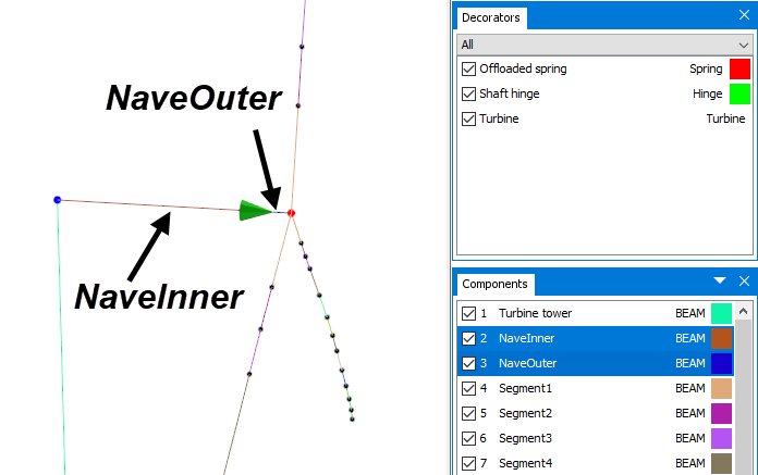
Further, we have three node decorators that are generated. These are:
- Offloaded spring
- Shaft hinge
- Turbine
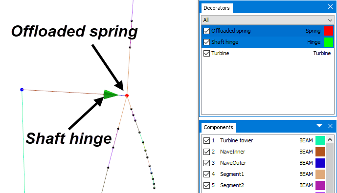
Offloaded spring
Double click on Offloaded spring from the Decorators-window to view the properties. This is a spring that is applied to stabilize the turbine blades in the initial static part of the analysis, prior to the dynamic analysis.
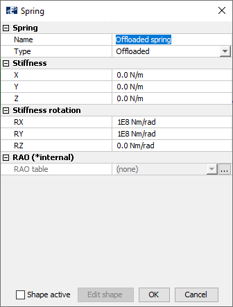
The spring works according to the global coordinate system, and rotational stiffness is given for both x- and y-direction. An offloaded spring has constant spring stiffness in the initial static part of the analysis and is offloaded when the dynamic part starts.
Shaft hinge
Shaft hinge is the generator. In AquaSim this is modelled as a hinge that is free to rotate about the axis that goes through the nave. Rotational damping is added to the hinge, which should be interpreted as the torque resistance. Double click on Shaft hinge from the Decorators-window to view the generator properties.
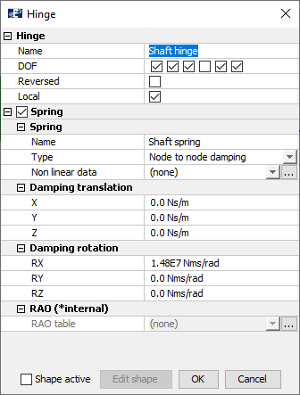
The generator has been given the name Shaft hinge. The section DOF indicates which degrees of freedom that should be restrained; selecting a checkbox means that the DOF is restrained. The three first checkboxes are translations along x-, y- and z-direction respectively. The three last checkboxes are rotations about the same axes. Local indicated whether DOF-restrictions should be related to the global coordinate system of the model, or the element’s local coordinate system. When this checkbox is selected, it means that the references are with respect to the element’s local coordinate system. This is indicated in the figure below.
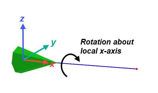
Rotational damping about this x-axis, RX, is added in the section Damping rotations. Select OK or Cancel to exit the Shaft hinge window.
Turbine
By double click on this you re-enter the Generate turbine-tool window.
Analysis
When conduction coupled analyses in AquaSim, one can find response and forces from combined effects such as:
- Environmental loads such as wind, waves and current.
- Loads from mooring systems.
- Loads from motions of the whole system.
From this, the coupled response is included from all load-contributions that will be present on a wind turbine that could be situated on land, offshore with fixed foundation or floating with a mooring system.
In this case study we will run an analysis to demonstrate the results options available for turbines in AquaView.
Select the Export-option from the top menu in AquaEdit to enter the window for inserting load conditions and to specify analysis settings.

Select the tab named Normal and apply regular constant wind of 8 m/s along x-direction. Set Num steps for waves equal to 400. Having 20 steps for one wave, this will result in an analysis of 20 seconds. This should be sufficient in to see the blades rotate about 1.5 times about the nave.
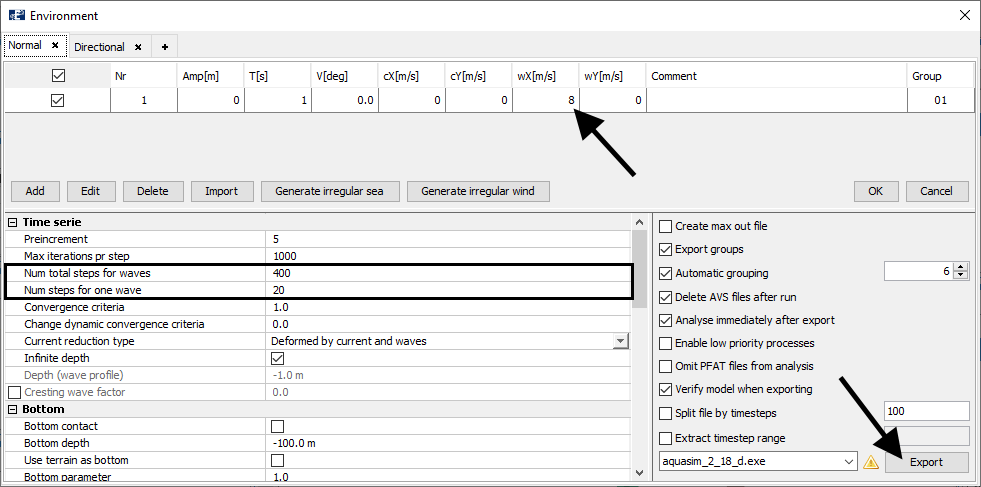
Select Export to export your model. Save the analysis an appropriate place on your computer. We named the analysis turbine_.

Post-processing (AquaView)
Once the analysis is finished you can load the avz-result file in AquaView. If you have not completed your own analysis, you may open the turbine_01.avz associated with this tutorial.
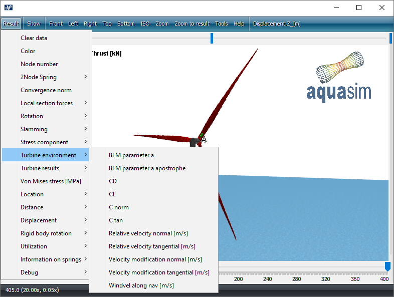
Results specially adapted to wind turbines are found from the top menu bar Result > Turbine environment and Turbine results.
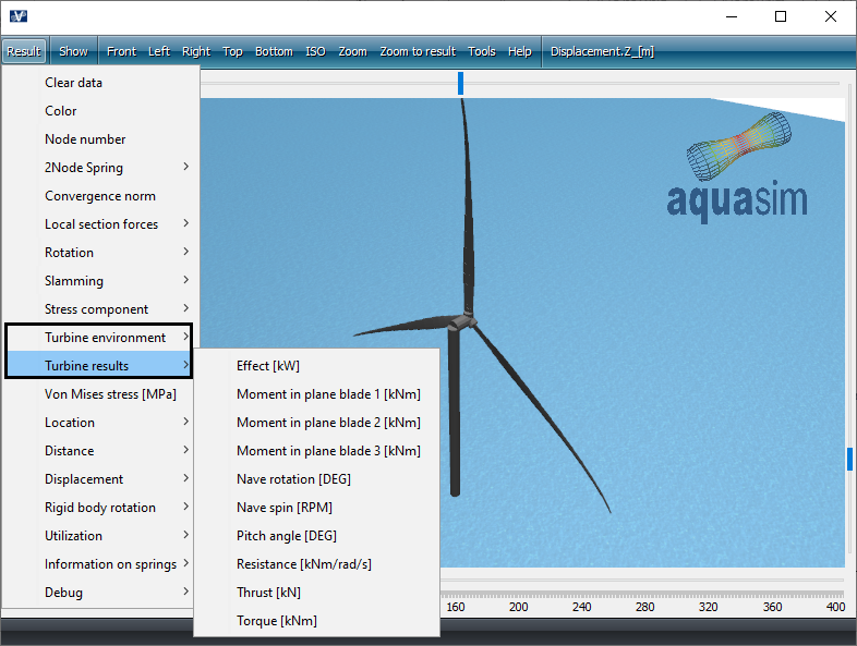
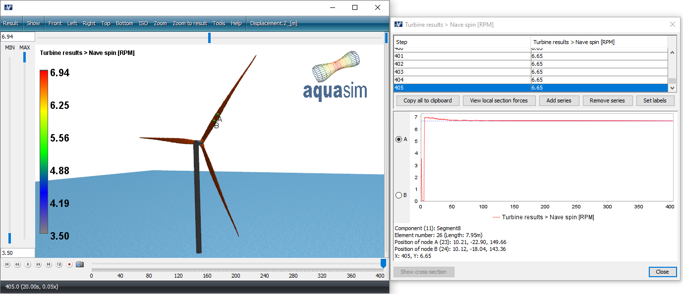
We should investigate some of the result options found under Turbine results. Let us start with Navne spin [RMP], this is the calculated velocity of the turbine blades. Right-click on one of the segments in the turbine blade to view the velocity as a function of analysis-steps.
During the analysis, the nave spin stabilize around 6.65 RPM, as seen in the figure below.
Another parameter that is interesting is the calculated torque. This is found from Result > Turbine results > Torque [kNm].
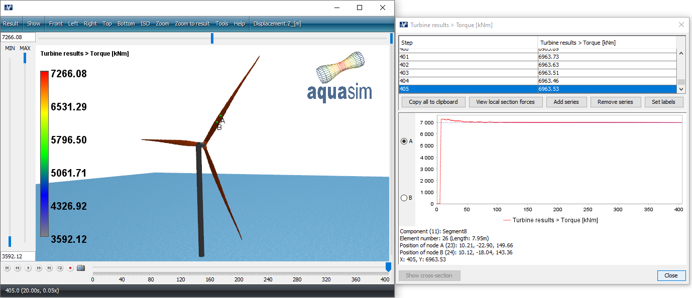
The torque shows the same trend as the velocity, it stabilizes around a certain level. In our analysis set-up we chose a wind velocity profile that was ‘flat’ and constant both in time and in space. So, the trend in the result plots correspond well with this.
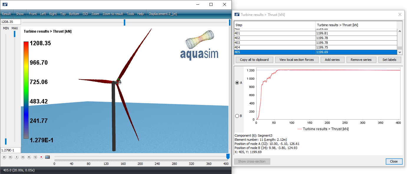
Thrust is the axial force applied from the wind on the blades.
Options found under Turbine environment are useful to check when validating your model and input-parameters. Details of these are found in the AquaView User Manual.
