Preprocessing
Last reviewed version: 2.18.0Establish the model in AquaEdit
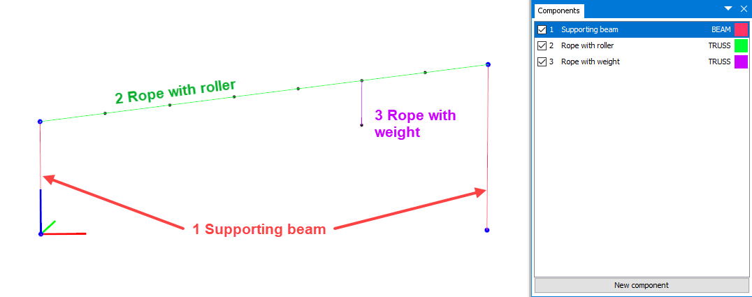
The model is based on the sketch given in the introduction. Create three component groups; one for supporting beams, one for a rope the roller should slide along and one for the rope attaching the weight.
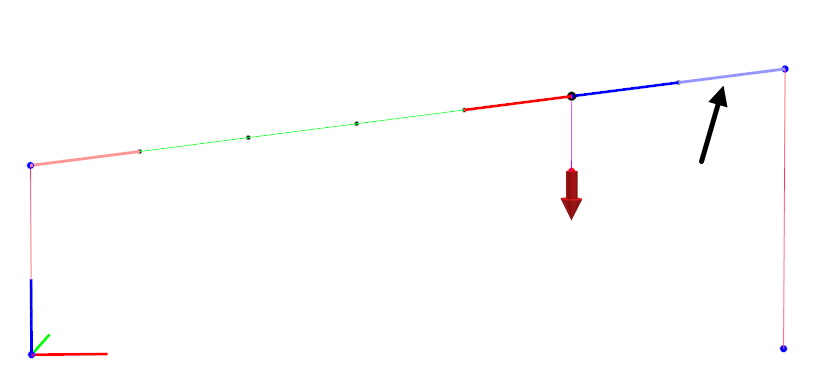
The main dimensions of the roller system are provided in the figure below.
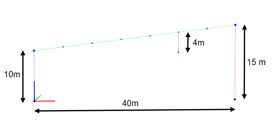
Discretize the component Rope with roller into 7 elements with equal lengths. The top- and bottom nodes of Supporting beams should be restrained from translation in x-, y- and z-direction.
Component properties
Suggested cross sectional properties for the three component groups are provided in the table below. Cross-sectional properties of the beam can easily be generated applying the Wizard found in the Edit-beam window.
| 1 Supporting beam | |
|---|---|
| Type | BEAM (Morison submerged) |
| Data source | Tube |
| Outer diameter | 100 mm |
| Thickness | 3 mm |
| Material | Steel |
| 2 Rope with roller | |
| Type | TRUSS |
| E-modulus | 2.1E9 N/m2 |
| Area | 1.45E-4 m |
| Weight in air | 0.257 kg/m |
| Diameter Y & Z | 0.014 m |
| 3 Rope with weight | |
| Type | TRUSS |
| E-modulus | 2.1E9 N/m2 |
| Area | 1.45E-4 m |
| Weight in air | 0.257 kg/m |
| Diameter Y & Z | 0.014 m |
The window for input cross sectional properties is accessed by double click the component group or, right click component group > Edit.
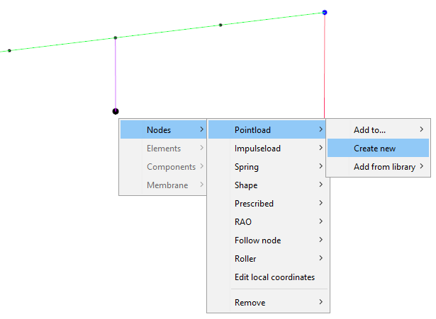
Add Pointload to rope (weight)
The purpose of the Pointload is to start the roller, so that it slides along the rope. Right click the lower node of Rope with weight > Nodes > Pointload > Create new.
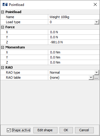
The Pointload should be a conservative node load of 100kg pointing in negative z-direction. Select Load type 0 and Force Z = -981.0 N.
Add roller
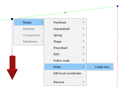
The roller should be assigned to the node intersecting Rope with roller and Rope with weight. Right click this node > Nodes > Roller > Create new.
The Roller decorator-window will open, and by default AquaSim have made some selection for you. This concerns especially what is regarded as the first-element of A and B, see figure below.
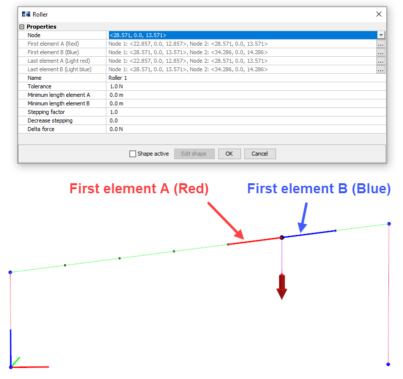
You should now define the last elements of A and B. This is where the roller will stop in each direction. The last element of A should be in the lower end of Rope with roller and the last element of B should be in the upper end.
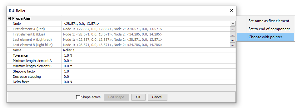
For Last element A (Light red), select Edit > Choose with pointer.
Then press the last element in the lower end of Rope with roller, as shown below.
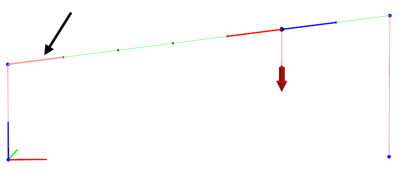
Repeat this for Last element B (Light blue), only now select the upper element of Rope with roller.
Roller parameters
The input-parameters applied for the roller in this case study is found in the figure below.
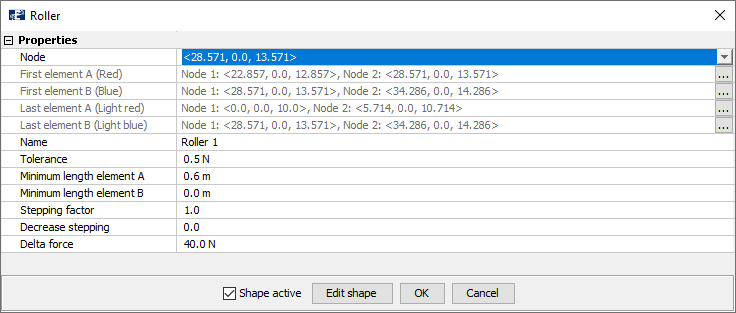
The roller Name is by default named Roller 1, this can be changed according to your preferences. Tolerance is set to 0.5N and Delta force is 40N, meaning that the element A should have 40N higher axial force than plus / minus a tolerance of 0.5N. So that the difference in axial force between element A should either be 40.5N or 39.5N. The Minimum length element A / B specifies the minimum allowed length of the elements on each side of the roller. In this case study, the minimum allowed length of the elements on the A-side of the roller is 0.6m.
The roller will stop when either the Tolerance / Delta force-criteria is fulfilled, or when the Minimum length element A / B is fulfilled.
Stepping factor and Decrease stepping are parameters regulating the iteration of the roller position. If Decrease stepping is larger than zero, the Stepping factor will be reduced during the roller iterations. These can be accelerated from the default values but enhances the risk of divergence.
Select OK and save the model.
Verify model
Your model is now complete. To verify that the model is correct and without errors, select Commands > Verify model.
You might be given a warning Loose node, this is due to the end-node of the Rope with weight not being attached to other nodes. This is acceptable because we want the Pointload in this node to induce the motion of the roller.