Case study – Tarpaulin closed compartment
Last reviewed version: 2.22Create analysis model in AquaEdit
The model is created in two main steps: first the tarpaulin, then the floater. The hemispherical tarpaulin can be modelled in several ways, here are two suggestions:
- Use the “Draw tube” tool and make a conical bottom. Then use the “Scale” functionality to make the cone a hemisphere.
- Use the “Draw circle” tool, half it and then use the “Extrude” functionality with rotation, to generate the hemisphere. The latter is chosen to be demonstrated in this tutorial.
Create tarpaulin closed compartment
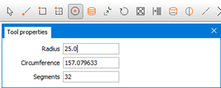
First establish a component type Membrane, then click the “Draw circle”, as illustrated in Figure 2.
The circle is centred in origin, and rotated to the xz-plane. Then delete the upper half of the circle as shown in Figure 3.
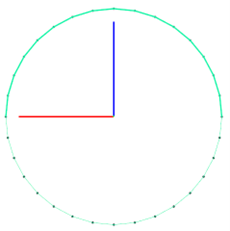
The remaining half of the circle is shown in the figure below.
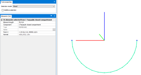
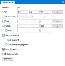
Select all the elements and click “Extrude”. Apply 16 segments and rotate 180 degrees about z-axis.
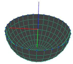
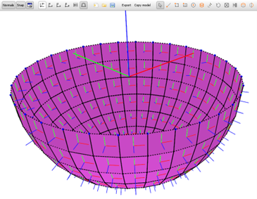
A hemisphere, as shown in Figure 6 is established.
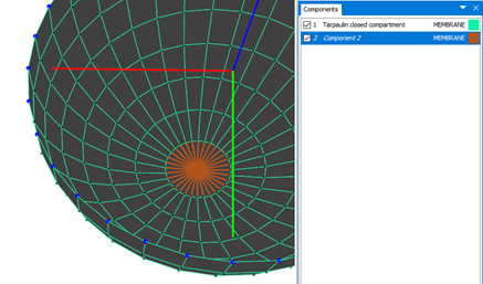
In order for triangular elements to be introduced to the membrane, the membrane needs to be of type MembraneX. Hence, the lines in the bottom part of the hemisphere are selected and moved to another component. This is illustrated in the figure below.
Then change the component type for “Tarpaulin closed compartment” from type Membrane to MembraneX. This is done by right-clicking the component select Type > MembraneX.
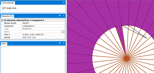
Triangular elements are added by utilizing “Draw membrane” and select “Triangular mode” in the Tool properties-section, see Figure 8. Remember to have the component “Tarpaulin closed compartment” selected.
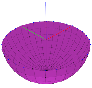
Draw the triangles to fill the bottom. When this is done you can delete the other component group. Now we have a complete hemisphere consisting of MembraneX, Figure 9.
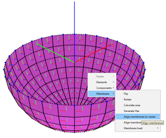
It is important for AquaSim to know which way the membrane panels are oriented. This can be checked through selecting the option Normals and then select alle the membrane panels, as seen below.
These should be centered towards geometric center. When all the panels are selected, right-click > Membrane > Align membranes to panel center. This is illustrated in Figure 11.
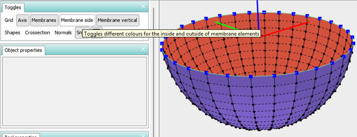
One may validate the directions by activating the “Membrane side” button as shown in Figure 12
Double-click the component type to enter the Edit MembraneX-window. Select Type: Normal and Load formulation: Closed compartment.
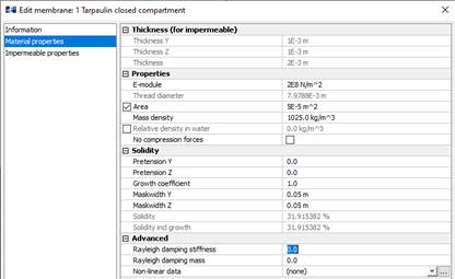
Figure 13 shows the material properties for this case study. Note that a mask width of 5 cm is chosen. This corresponds to standard width of test-specimens when determining material data for tarpaulins. If the tarpaulin has different properties in warp and weft directions, one must have a different mask width in the other direction.
Then parameters for in Impermeable properties has to be defined, this is shown in Figure 14
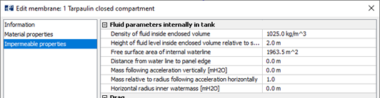
- Density of fluid inside enclosed volume: this is the density of the internal fluid. Normally 1025kg/m3 for seawater and 1000kg/m3 for fresh water.
- Height of fluid level inside enclosed volume relative to sea level: this is the height of the water (positive upwards) of water inside the enclosed volume. This is the waterline in the drawn not-deformed structure. This determines the volume of the inside fluid. This volume is assumed constant during the analysis, such that if the structure deforms downwards in the way that the volume below the waterline becomes larger, the height of fluid will decrease and vice versa.
- Free surface area of internal waterline: this is the area of the water surface inside the enclosed volume. This is assumed constant in the analysis. And if the volume below the waterline increases, the fluid height will decrease.
- Distance from water line to panel edge: this parameter is set in case one would like to include that the water pours out if it exceeds this value (this is relative to the lowest point of the upper line on the enclosed volume). Note that there is no mechanism working the other way around, such that the total water volume can only decrease as analysis progresses.
Create floater
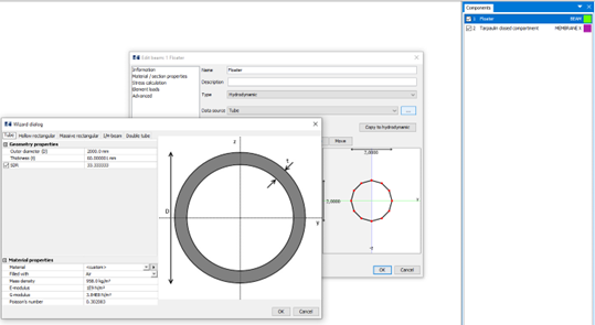
A simplified floater is created by establishing a beam component and drawing a circle along the top of the tarpaulin closed compartment. Use the AquaSim built in Wizard to create a tube, see Figure 15
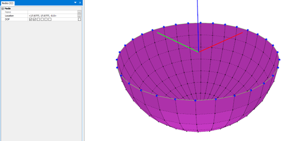
Since the model is a simplified structure not including mooring, the nodes along the floater are restrained from horizontal motions, see Figure 16.
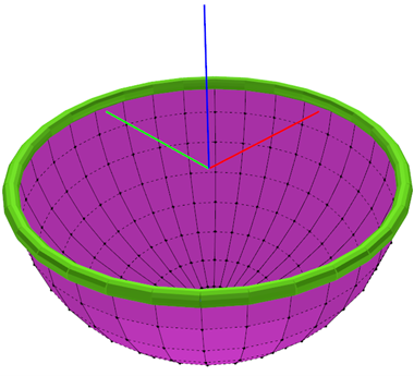
Now we have a complete model in Figure 17.
Since we do not want AquaSim to change the orientation of the membrane normal, remember to check on the “Membrane normals are verified” in the Export-menu. A static analysis (without current) is run.