Beam – Type 1 (mean wind)
Last reviewed version: 2.18.0AquaEdit
In this first example we are going to look at wind type 1 for beam elements. The basic assumption for wind type 1 is that the elements in the component group represents a ship shaped structure horizontally in the water line. This type of wind is supposed to represent wind fetch on parts of the hull not being modelled, but where there is an actual wind exposure.
Open the AquaSim model WindType1.amodel that is associated with this tutorial.
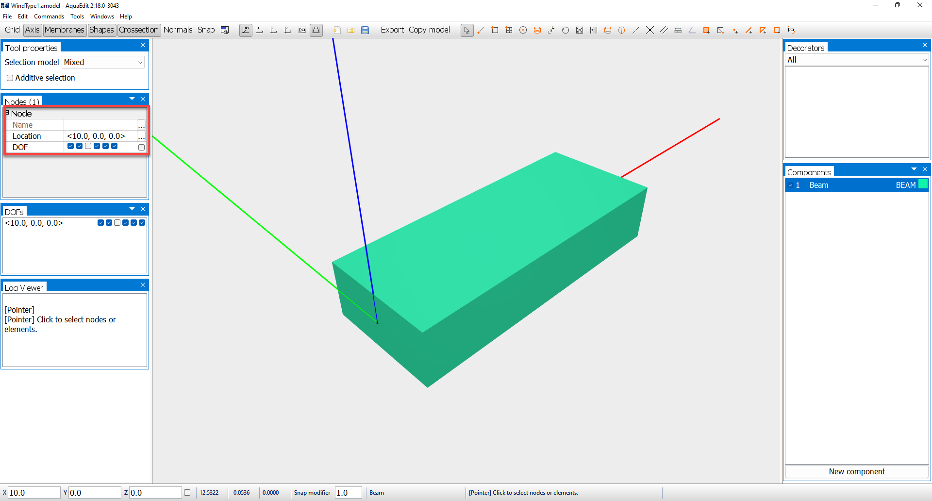
A simple one-element beam is modelled along the x-axis. One of the nodes are fixed, except for the z-direction. Options for including wind is found in the Edit beam window. Doble click on Beam in the components window and go to the Elements-tab.
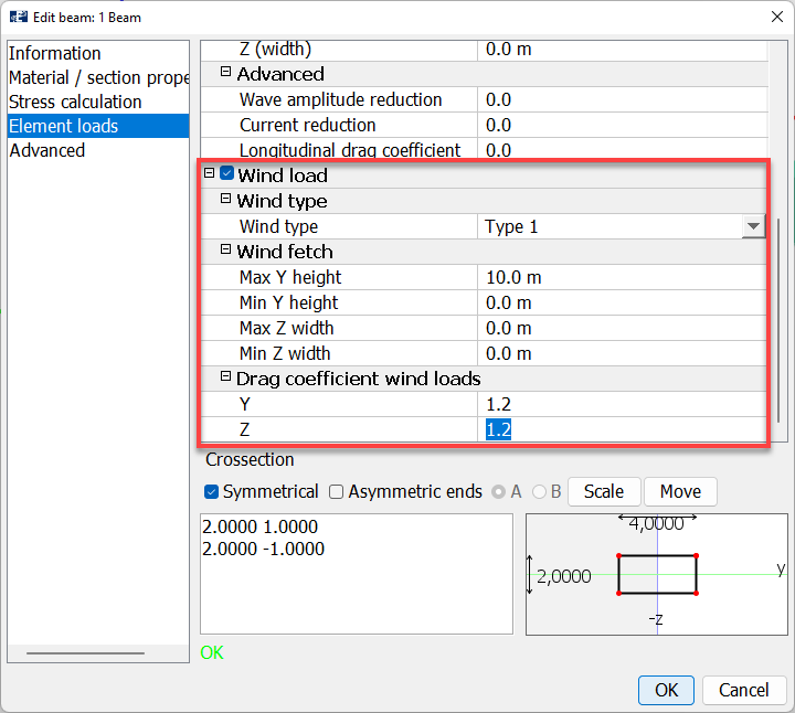
Wind loads are activated by toggle on the checkbox for Wind Load. Then a menu with sections for defining the Wind type and Wind fetch becomes available. From the drop-down menu in Wind type, select Type 1.
Type 1:
Apply wind on the elements according to a user-defined wind fetch area.
Wind fetch:
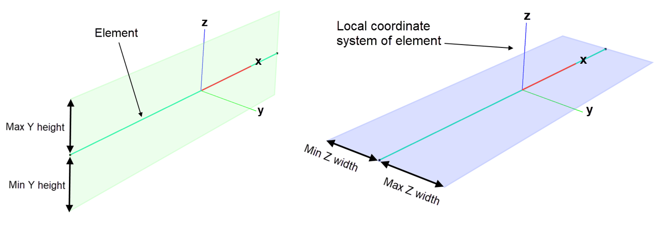
Defines the area that is exposed to wind. This can be extended further than the size of the cross section itself. AquaSim assumes a square cross-section, where the input is:
- The Max Y height, and Min Y height means to set wind fetch area transverse to the element direction. Max / Min Y height is one side of the square, and the element length is the other.
- Max Z width and Min Z width means to set wind fetch area lateral to the element. This is useful if the ship rolls, then the deck also can be exposed to wind. Max / Min Z width is one side of the square, and the element length is the other.
Drag coefficient wind loads set the drag coefficient for the local y- and z-direction. Apply the values 1.2 for both Y and Z. Select OK.
The wind velocity itself is defined in the Environment window in the Export menu.
Analysis
Open the Export menu and select the Normal-tab.
Mean wind can be defined in both x- and y-direction. In the load condition line, these are identified as wX[m/s] and wY[m/s]. In this case study, a mean wind velocity of 30 m/s is applied in the y-direction. A logarithmic wind profile is assumed, and it is the 10-minute mean wind, 10 meters above the mean water line that is the input.
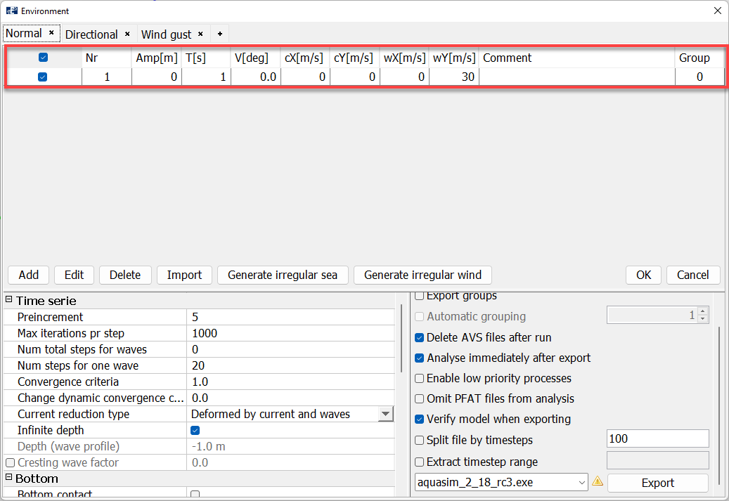
Go down to the Time serie section: mean wind is applied in the initial static steps in AquaSim. We leave Preincrement = 5 and set Num total steps for waves = 0. In this way, only the static steps will be considered.
To start the analysis, select Export in the lower right corner of the Environment window. Save the analysis a suitable place and Start the analysis. We have named the analysis type1_mean_.
Note: if you run the analysis in batch-mode, the CMD window will appear and view the status of the calculated steps. This is the same text that will appear if you select Show messages in the Analyse-window.
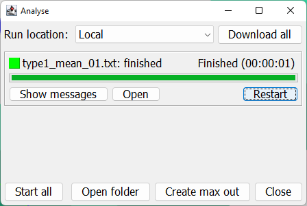
The analysis should be finished within seconds. Open the result file in AquaView through selecting Open from the Analyse window.
AquaView
In AquaView, we choose to view the shear force in y-direction. Select Result > Local section forces > Shear force Y [N].
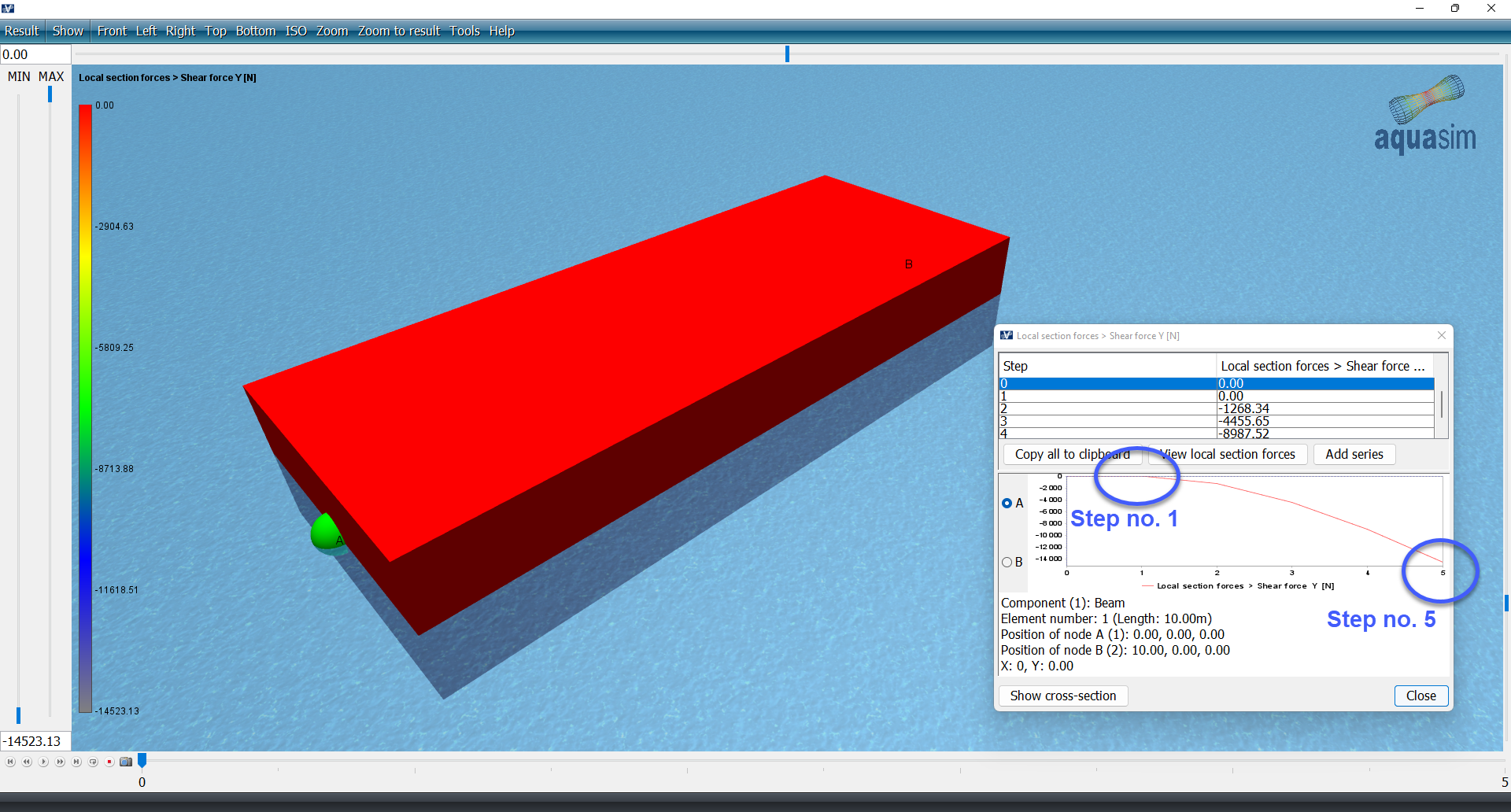
Wind is linearly increased from zero to its full value according to the number set in Preincrement in the Export menu. Therefore, the shear force is zero in the first analysis step. It is fully developed in step number 5. Ok, so this was mean wind for beams with wind type 1. In the next section, we investigate wind gust.
This was an introduction to mean wind for beams with wind Type 1. In the next section, we investigate wind gust.