Membrane (mean wind)
Last reviewed version: 2.18.0Wind can also be applied to Membrane components. In this case study, a membrane of type Normal in combination with the Load formulation Normal is presented.
Open the AquaSim model Wind_Membrane.amodel in AquaEdit. This is a simple model with 3 one-element membrane panels at three different vertical locations.
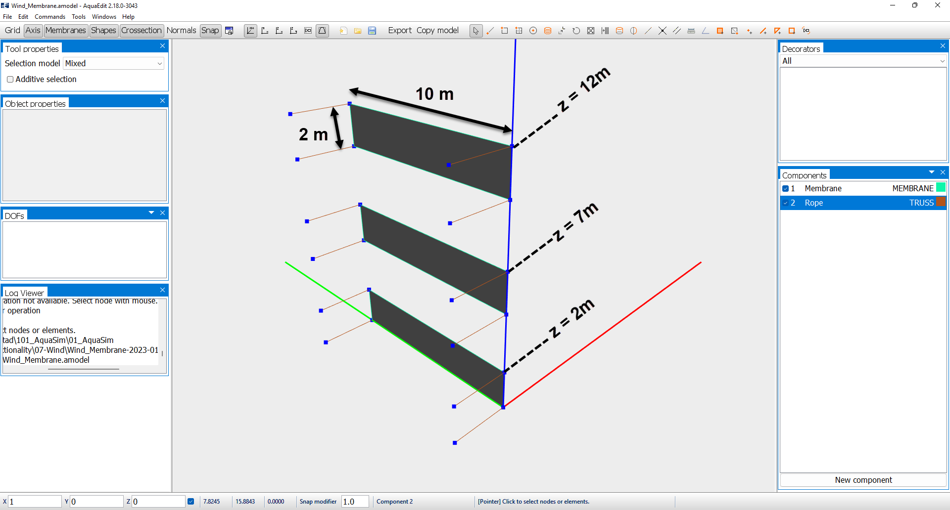
The panels are restrained from moving in all degrees of freedom, except from x-direction. In addition, the panels are restrained with ropes on the x-direction. When wind is applied along x-direction the wind forces on the panels are reflected in the ropes.
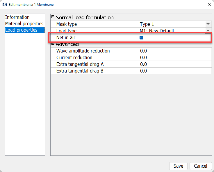
In AquaSim, mean wind is included for membrane panels of type Normal when the Net in air selection is toggled on. This is found the Edit Membrane window, in the Load properties tab.
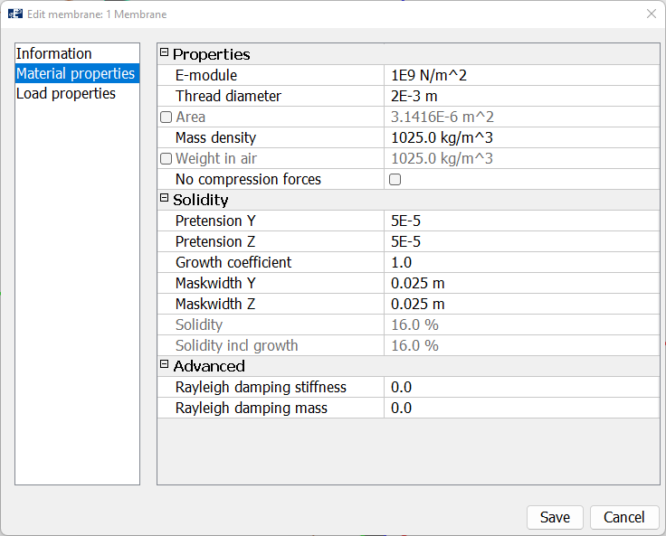
The properties of the membrane may be reviewed in the Material properties tab.
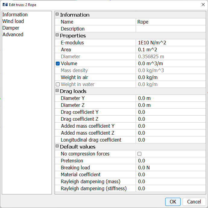
We are satisfied with the defined values and select Save. The cross sectional properties of the ropes are found in the figure below. It is assigned some stiffness, but the volume and weight are set equal to 0. In that way, the ropes will only contribute to restrain the panels and to take up axial forces. They will not contribute to aerodynamical forces.
The wind velocity itself is defined in the Environment window in the Export menu.
Analysis
Select Export and navigate to the Normal-tab. The setup is equivalent to what was presented in the first case study with the Beam exposed to mean wind, only that the wind is applied along the x-direction. Hence, wX[m/s] =30.
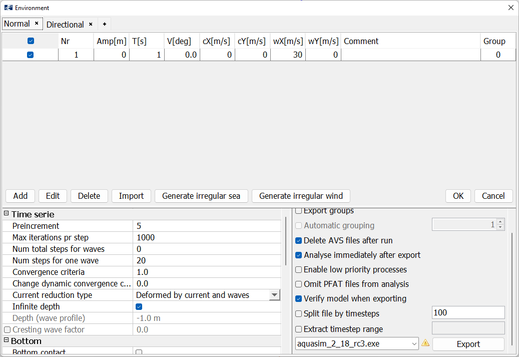
Only the static part of the analysis is considered. Preincrement is set to 5 and Num total steps for waves are equal to 0.
Analysis
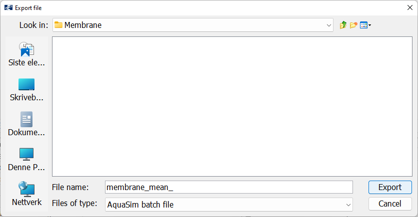
Export the analysis and save it a suitable place. We have named the analysis membrane_mean_. Start the analysis.
When the analysis is finished, Open it in Aquaview.
AquaView
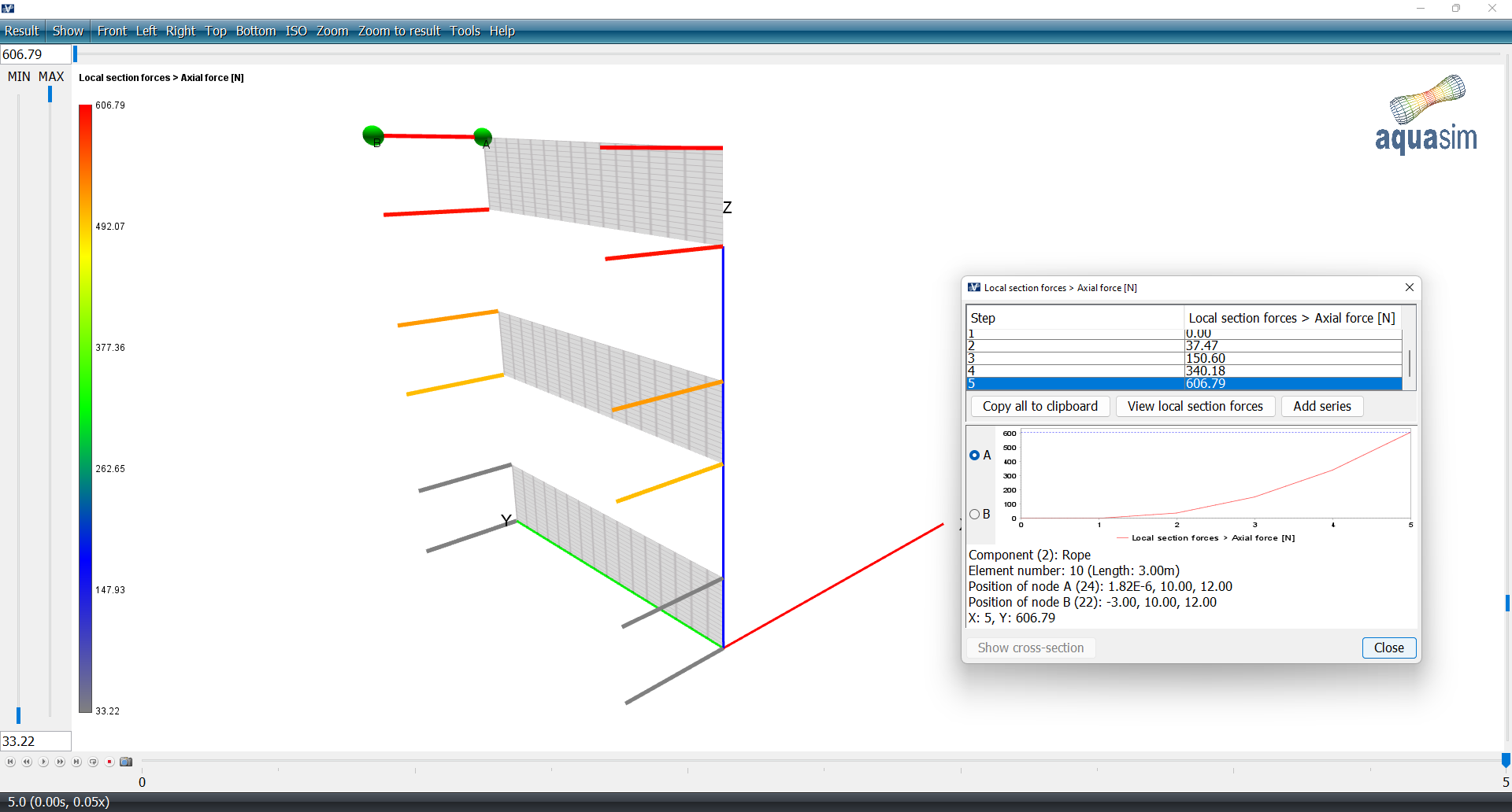
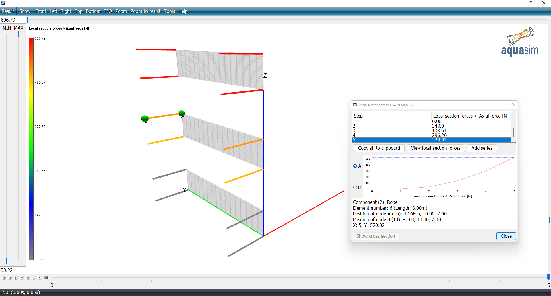
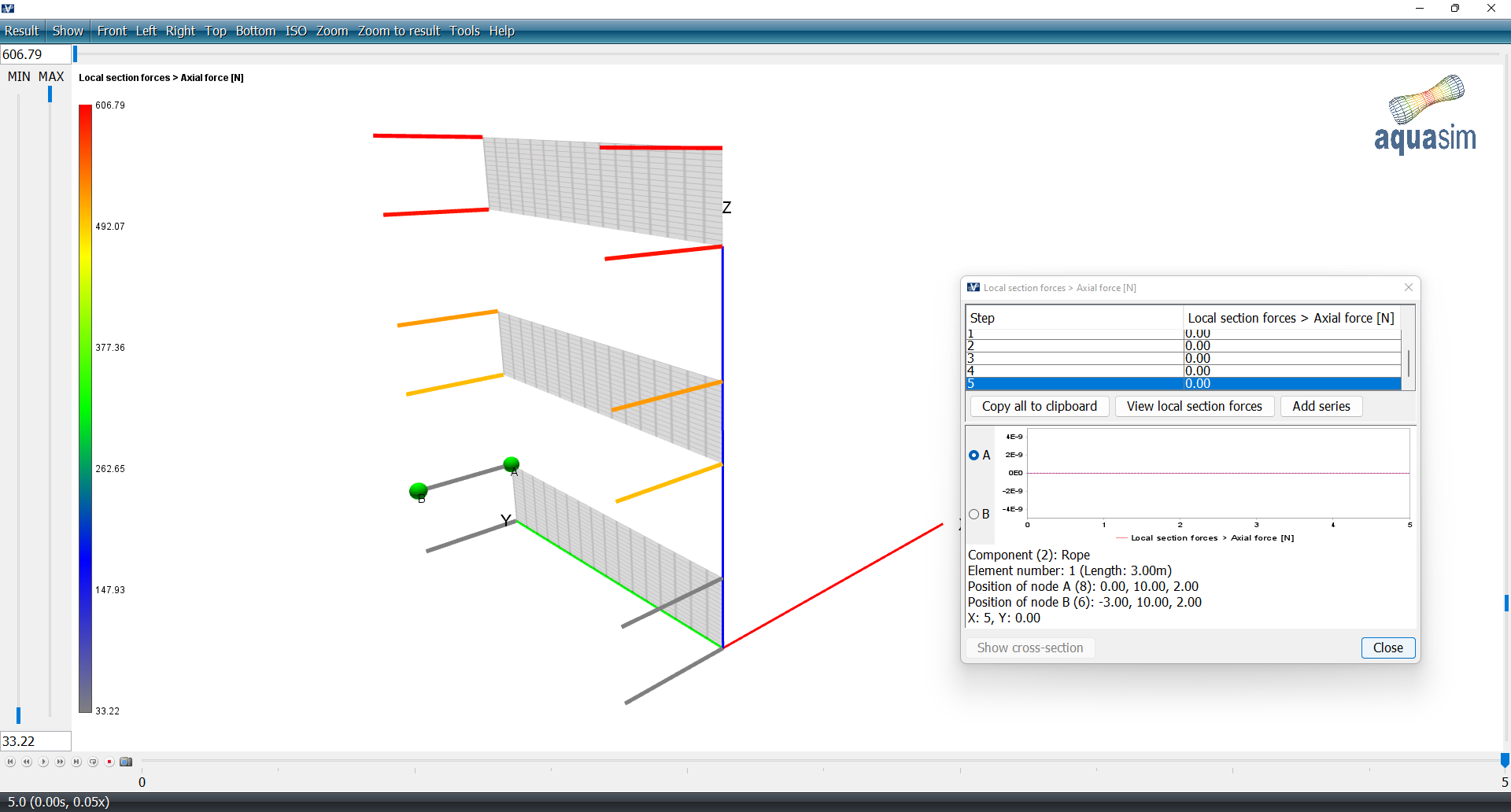
We should plot the axial forces in the trusses, select Result > Local section forces > Axial forces [N] and select the truss elements in the 3D window.
AquaSim apply a logarithmic wind profile. This will result in different values of wind loads at different elevations. This is seen by the axial forces in the ropes vary with the panels. The highest panel is exposed to a higher wind load than the lower ones.
