Modelling watertank
Last reviewed version: 2.22A basic tank can be modelled using the tool Generate Net in AquaEdit, as shown in Figure 1.
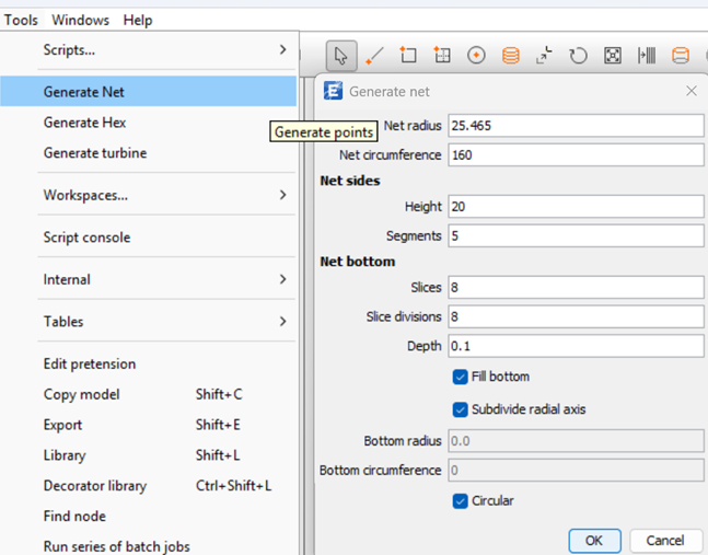
Figure 1 Generate net option in AquaEdit
The Depth parameter can be set to zero, or to a small value, in order to create a flat or nearly flat bottom surface for the tank. The generated geometry will then consist of both the side walls and the bottom, as illustrated in Figure 2. To represent a land-based tank (i.e. a structure located in air), the model should be positioned such that its baseline is at z = 0 or higher. This ensures that no external water loads are applied.
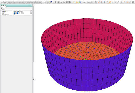
Figure 2 Tank walls and bottom modelled in AquaEdit
The orientation of the membrane panel is important to make sure that pressure is calculated correctly, in Figure 2 the option Membrane side is activated. The inside of the tank should have a shade of red color and the outside a shade of blue.
Enter the Edit membrane dialogue by double clicking the component in the Components section, as illustrated in Figure 3.
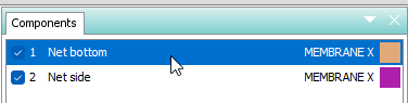
Figure 3 Enter Edit membrane dialogue
The membrane type should be Shell, and to include the effect of the water inside the tank, the Closed Compartment option must be activated. This enables AquaSim to calculate the internal hydrostatic pressure acting on the structure.

Figure 4 Shell properties and Close Compartment option
The tank dimensions used in this tutorial are given in Figure 5.
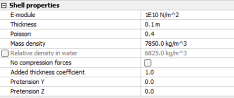
Figure 5 Tank dimensions
This tutorial focuses on a simple, unstiffened tank. The section properties in Figure 4 may be interpreted as equivalent values representing a full cross-section, including all layers in the case of composite construction, and accounting for stiffeners where relevant. More complex tank configurations are not covered here but can readily be modelled by applying standard AquaSim elements such as stiffened panels.
The parameters defining the internal fluid are shown in Figure 6:
- Density of fluid inside enclosed volume – the density of the water contained in the tank; in this case fresh water with a density of 1000 kg/m³.
- Height of fluid – the fluid level expressed relative to the coordinate system. For a fully filled tank, this equals the top of the tank, in this case z = 20 m.
- Free surface area of internal waterline – the area of the free water surface inside the tank; in this case 1963.5 m².

Figure 6 Fluid parameters for the internal water volume
The nodes along the tank bottom are fixed in all DOFs, representing a rigid foundation support. This is illustrated in the left part of Figure 7
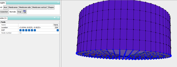
Figure 7 Fixed boundary conditions at tank bottom
The nodes along the upper rim are released in horizontal directions and in rotation, as shown in Figure 8.
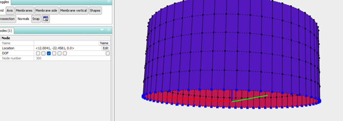
Figure 8 Boundary conditions at nodes along the rim