Analysis of Cable with Buoyancy Segments
Last reviewed version: 2.22
Learning Objectives
Upon completion of this case study, you will be able to:
- Model a cable with bending stiffness in AquaSim, including definition of structural and hydrodynamic properties for segments with and without buoyancy elements.
- Apply prescribed displacements and rotations to position the cable correctly and establish a realistic layout prior to dynamic analysis.
- Define and apply an RAO to a vessel attachment node to represent vessel motions in a seaway.
- Defining bottom contact springs on nodes with seabed-contact and understanding how spring stiffness affects convergence.
- Perform a static equilibrium analysis to verify pretension, cable geometry, and Von Mises stress in the layout condition.
- Run dynamic analyses in both regular and irregular seas, including the specification of wave and current environmental data.
- Post-process and interpret results including axial forces, vertical displacements, and curvature along the cable length and as time series at selected locations.
Introduction
Offshore cables and risers are often equipped with buoyancy elements to control their configuration and dynamic behavior in water. Accurate modelling of such systems requires consideration of structural stiffness, hydrodynamic loads, seabed interactions and vessel motion. Figure 1 illustrates a typical cable configuration attached to a vessel, with buoyancy segments. The cable is subject to waves and current, while interaction with the seabed influences the overall geometry and tension distribution.
This tutorial demonstrates how such system can be modelled in AquaSim. The case study includes establishment of the initial cable layout, application of environmental loads, and evaluation of key response parameters such as tension, displacement and curvature.
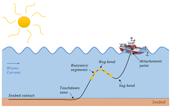 Figure 1 Cable system with buoyancy segments
Contrary to a regular mooring line, a cable with bending stiffness requires a more detailed structural model to capture its true mechanical behavior. The analysis is benchmarked against results from widely used commercial offshore analysis software, demonstrating that AquaSim produces results in close agreement with established industry tools for this class of problems
Abbreviations and definitions
The following abbreviations and definitions are included to clarify terms and concepts used throughout this tutorial.
RAO (Response Amplitude Operator): is a frequency domain transfer function that describes how a floating vessel responds to waves. For a given wave frequency and direction, the RAO defines the vessel motion amplitudes and phases in all motion directions (surge, sway, heave, roll, pitch and yaw). In this tutorial, the RAO is used to apply realistic vessel motions in the cable attachment point.
DOF (Degrees of Freedom): describes a direction in which a node or body can translate or rotate. In three-dimensional structural analysis, a node can have up to six DOFs: three translations (x, y, z), and three rotations (about x, y, z). In this tutorial, selected DOFs are fixed, prescribed or controlled by the RAO.
Stress-free condition: the shape and state of the cable when it has no external loads. In this tutorial this is defined as the condition where the cable is in a straight and unloaded configuration, without any residual stresses from manufacturing. Strained condition: the shape and state of the cable when it deforms into a specific shape due to e.g. internal strain, weight and external loads.