Analysis of predator net
Last reviewed version: 2.22The analysis parameters used for the simulation are presented in Figure 10.
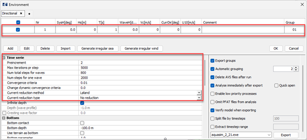
Figure 10 Analysis parameters
Since contact simulations are highly non-linear, the choice of analysis parameters might need several initial tests for achieving stable and physically realistic results. It is generally recommended to start out with simplified test analyses, such as this case study, before proceeding with the final simulation.
Results
This section presents results from the impact analysis and demonstrates how results can be evaluated in the post processor AquaView. When post processing, the main purpose is to verify that the contact simulation behaves as expected, evaluate the predator motion before and after impact, how the contact forces propagate through the net structure, and assess stresses and response in the area where impact occurs.
Figure 11 illustrates the vertical position of the predator and the net at the initial position.
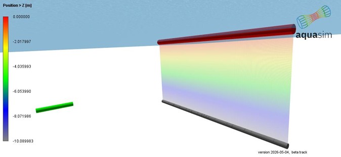
Figure 11 Vertical position of net system.
Figure 12 shows the velocity of the predator during impact. Initially, the predator beam is accelerated using the prescribed time RAO, and the offloaded spring system as described in previous sections. The velocity increases until the target in the RAO is reached. Then the RAO is no longer active. This is seen in the first part of the time-domain simulation in Figure 12. In the moment of impact, the velocity drops significantly due to transfer of kinetic energy from the predator beam to the net.
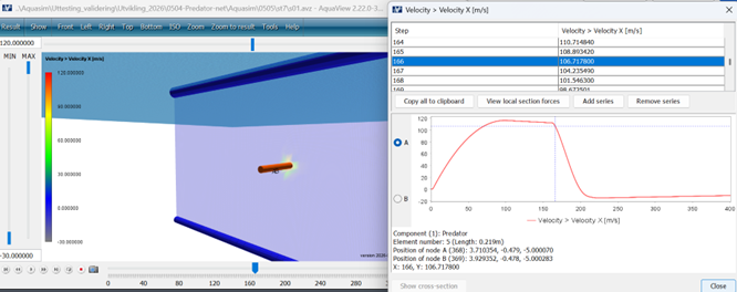
Figure 12 Predator velocity
Figure 13 - Figure 15 illustrates the stress distribution in the net during impact. Due to the flexibility of the net, the deformation and stress propagate through the surrounding mesh. Initially, the stresses are concentrated to a small region in the impact zone. This is seen in Figure 13. As time progresses, the contact forces are distributed through a larger part of the mesh.
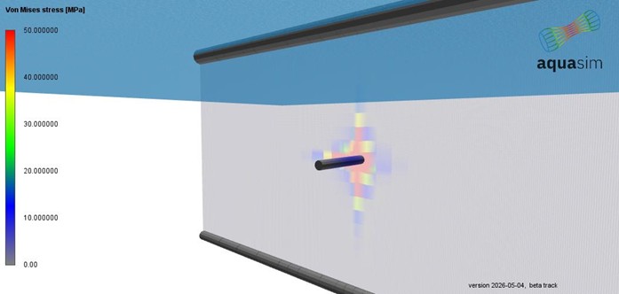
Figure 13 Right after impact
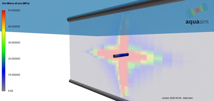
Figure 14 More milliseconds after impact
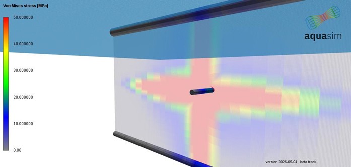
Figure 15 More milliseconds after impact
By reviewing the animation in AquaView, one can investigate when contact is initiated and how the contact forces are distributed over time. This is useful when it is necessary to identify regions with local high stresses, possible requirements for local reinforcements and general load transfer between construction parts.
Summary
This tutorial has demonstrated how to model and analyze marine predator attacks on fish net structures using the Component contact functionality in AquaSim.
The key steps covered include:
- Modelling the fish cage net with local mesh refinement in the expected impact zone
- Modelling the predator as a self-buoyant beam element with realistic mass properties
- Applying a time RAO and offloaded springs to accelerate the predator to a target velocity prior to impact
- Defining Component contact parameters — including contact spring stiffness, damping, and contact distance/radius — in the Tools–Tables section
- Running a dynamic time-domain analysis and evaluating results in AquaView
The contact force follows a nonlinear relationship with the relative displacement between the two components, meaning forces build rapidly as contact deepens. This will require calibration of the contact spring stiffness and the Distance/Radius parameter to achieve numerical convergence.
Post-processing in AquaView allows to track predator velocity, monitor the progression of stresses and forces in the net elements during and after impact, and follow how contact forces propagate through the structure over time.
Although this tutorial uses a simplified beam to represent the predator, the same modelling approach applies to any impacting body; including marine mammals, drifting objects, vessels, ROVs, or similar.
References
- Aquastructures. (2026a, 05 07). Component contact: Falling box. Hentet fra aquasim.no: https://aquasim.no/documentation/componentcontact.html
- Aquastructures. (2026b, 05 07). Safety net. Hentet fra aquasim.no: https://aquasim.no/fields/safetynet.html