Pre processing
Last reviewed version: 2.18.0Establish the model in AquaEdit
You may either create the model from scratch or apply the AquaSim model following this tutorial. The model is based on the sketch given in the introduction. Four component groups are created; Beam, Rope 1, Rope 2 and Loop. The Loop should be able to slide along Rope 1. Five node decorators are also created; Weight 1, Weight 2, Roller 1, Roller 2 and Buoy.

The main dimensions of the modelled system are provided in the figure below.

Components Rope 1 and Rope 2 are discretized into 5 elements with equal lengths.
Component properties
Applied cross sectional properties for the four component groups are provided in the table below.
| Beam | |
|---|---|
| Type | Type BEAM (Morison submerged) |
| E-modulus | 2.1E11 N/m2 |
| G-modulus | 8.08E10 N/m2 |
| Area | 0.01 m2 |
| Iy and Iz | 0.01 m4 |
| It | 0.01 m4 |
| Volume | 0.0 m3/m * |
| Weight in air | 0.0 kg/m * |
| Rope 1, rope 2 and loop | |
| Type | TRUSS |
| E-modulus | 2.1E9 N/m2 |
| Diameter | 0.028 m |
| Weight in air | 0.73 kg/m |
| Diameter Y and Z | 0.028 m |
| Drag coefficient Y and Z | 1.2 - |
| Added mass coefficient Y and Z | 1.0 - |
*) The beam should not contribute to weight or buoyancy in the analysis, this is why these parameters are set equal to zero.
Boundary conditions
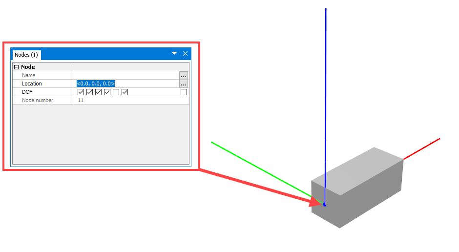
The beam should be applied some boundary conditions. The first node is defined in (x, y, z) = (0, 0, 0) and the second node at (x, y, z) = (2, 0, 0). The first node is restrained from translations and rotations, except from rotation about y-axis as illustrated in the figure below.

The second node is not restrained.
Spring type: Buoy
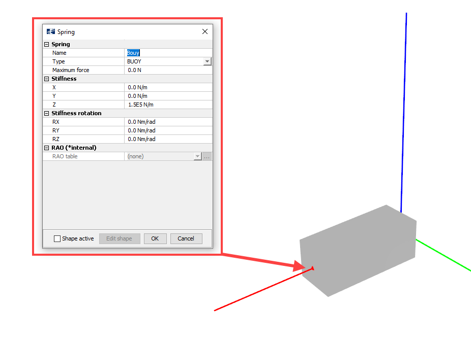
In this case study we want the beam end, that is not restrained, to follow the wave motions up and down. Therefore, we add a spring of type BUOY at this end. Right click the node > Nodes > Spring > Create new. Properties of BUOY is shown below.

Weights
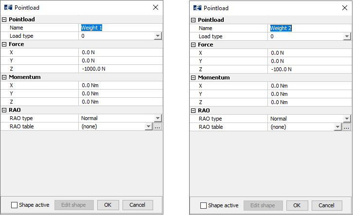
The weights in the end of Rope 1 and Rope 2 are applied as Pointload of type 0. The properties are shown below.

Weight 1 should have a force in z-direction of -1000 N. Weight 2 should have a force in z-direction of -100 N.
Rollers
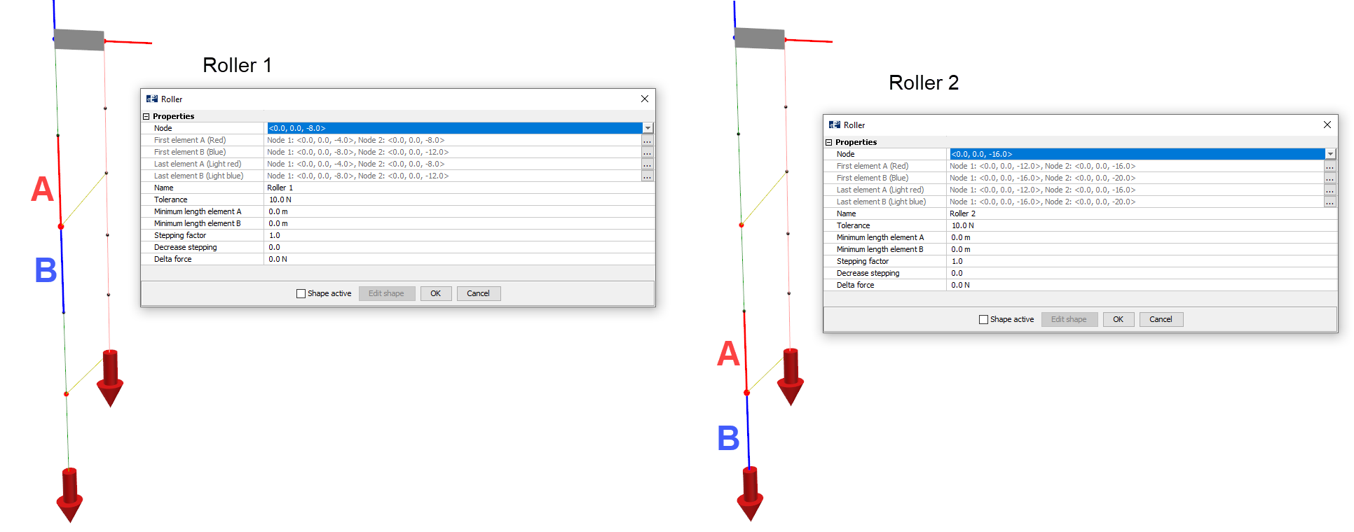
One roller is assigned to each of the nodes that is sheared by Rope 1 and Loop. The implementation and values are illustrated in the figure below.

Tolerance is set to 10 N for both rollers. When we have Tolerance = 10N and Delta force =0 N, the timestep will converge when the difference in axial force between element A and B are lower than Tolerance. For more information about how Roller is applied, and the other parameters, reference is made to the tutorial Roller found on aquasim.no.
Verify model
Your model is now complete. To verify that the model is correct and without errors, select Commands > Verify model.
You might be given a warning Loose node, this is due to the end-node of the Rope 1 and Rope 2 not being attached to other nodes. This is acceptable because we want Weight 1 and Weight 2 to apply tension in the ropes so that they are kept straight.