Creating the model
Last reviewed version: 2.16.4Generate beam component
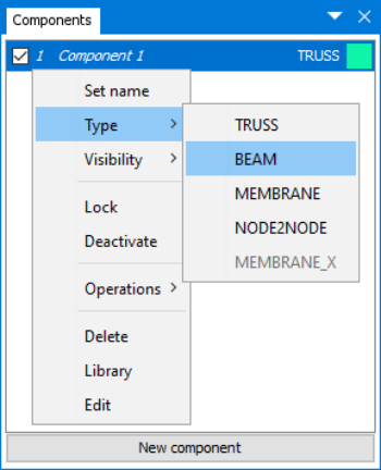
You are to establish a BEAM component. In the Components window, AquaEdit by default present the first component as type TRUSS. To change this, right click 1 Component > Type, select BEAM.

Select the intent Draw line  from the Toolbar menu.
Move the mouse pointer down to the lower most toolbar to type the coordinates of the first node, X=0 Y=0
Z=0  , press ENTER on your keyboard.
Now, select the checkbox to the right of coordinate Z. This will activate relative
coordinates to the first defined node, type X=0 Y=0 Z=-20  , press ENTER on your keyboard.
Then, exit the Draw line intent by selecting Pointer, or press ESC three times. You should now have one element connected with two nodes, in your 3D viewer.

Properties of Beam component
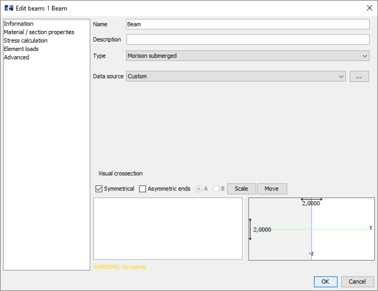
You should give the beam cross sectional properties by accessing the Edit beam window. Note that the component name is in italic, this indicates that it lacks essential properties for analyzes to be performed. Right click 1 Beam > Edit.

In the Edit beam window, the first view you meet is the Information-tab. In the Information-tab you may assign general information to your beam and either draw a cross section from predefined sections or access AquaCross for customized sections. In the row Name, type the component name Beam.

Press the drop-down menu from Data source > Massive rectangular.

The wizard dialogue for predefined sections is opened. Change Material from Plastic to Steel. Press OK, and then OK in the Edit beam window

The name of the component should have changed from italic to straight font, meaning the beam has adequate properties.

Save the model
Good saving routines during modelling is important to ensure that work is not lost. In the top menu, select File > Save as…

Navigate through the File Explorer to a suitable place to save your model. In this case study, we have created a folder in Documents\AquaSim called Analyses\CaseStudy01. Assign model name Beam and press Save.
Assign boundary conditions
The cantilevered beam should be restrained from translation and rotation at the top end and exposed to a point load in x-direction at the lower end.
In the 3D view, use the mouse pointer and click on the node in the origin of the global coordinate system. The Nodes property window will be activated in your left docking area. In the row DOF (Degrees Of Freedom), select all the checkboxes.

In the DOF row (counted from left to right): the first three checkboxes represent translation about x-, y- and z-axis respectively. The three last checkboxes represent rotation about x-, y- and z-axis respectively. One selection represents a constraint, so when all the checkboxes are selected the node is restrained in all Degrees Of Freedom. Having one or more restraints, the node in the 3D view will change from black to blue.
Assign point load
The point load is to be assigned to the free end of the beam. In the 3D view, use the mouse pointer to select the free end of the beam. Right click > Nodes > Pointload > Create new

In the Pointload window, type Force X=1000. The directions for force and momentum are applied with respect to the global coordinate system. A positive value in x-direction correspond to a force acting in the positive x-direction. Click OK.

The Decorators window in the docking area to the right lists the node decorators in the model. In addition to Pointload, nodes may have decorators such as impulse load, spring, shape and more.
In the 3D view, the node with the Pointload change color from black to red. In addition, the arrow indicates the direction of the applied load.

Verify model
The model is complete. To verify the model is correct and without errors, select Commands > Verify model. If the model has errors, AquaSim will suggest solution to fix it. Read more about errors and warnings in the AquaEdit User Manual
