Analysis model
Last reviewed version: 2.22There has been performed analysis of a vertical cylinder modelled with “Membrane” elements as shown in Figure 5, with normal vectors pointing inwards and with parameters as described in Table 2 and Figure 8, previously used in (Aquastructures AS, 2025b). The diagonal of the “Membrane” elements has a length of 1.34m, meaning that one can expect sufficiently accurate results for wave periods T≥2.3s, when using “Numerical diffraction”, according to the methodology described in (Aquastructures AS, 2025a).
Furthermore, there are modelled a frame consisting of “Beam” elements along the vertices of the “Membrane” elements, a vertical centre beam and eight symmetrical horizontal radial beams at the top of the cylinder, as shown in Figure 6, with parameters as presented in Figure 7.
There is also modelled a “Truss” element at the top of the cylinder, as seen in Figure 5, with properties as shown in Figure 9.
In the analysis model, all nodes are restrained to only be able to move in the global x-direction (along red axis), except the node at the end of the horizontal truss element at the top of the cylinder, which is restrained in all degrees of freedom (DOF).
| Description | Value | Unit |
|---|---|---|
| Length, L | 110 | m |
| Diameter, D | 10 | m |
| “Membrane” elements, circumferentially | 32 | # |
| “Membrane” elements, longitudinally | 110 | # |
| “Membrane” elements, total | 4032 | # |
| Wave amplitude, ζ | 1.0 | m |
| Wave period, T | See Figure 10 | s |
| Wave direction | 0 (along positive x-axis, i.e. red axis in Figure 5) | deg |
| Number of steps per wave period [-] | 160 | # |
Table 2 Description of analysis model.
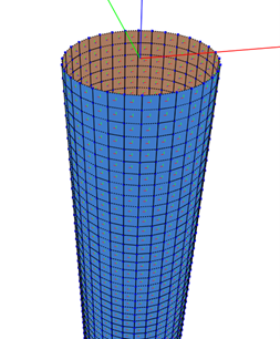
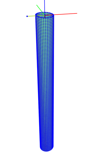
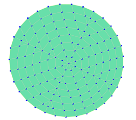
Figure 5 Analysis model of vertical cylinder with a length of 110m and diameter of 10m. Illustration of orientation of normal vectors to the left, full model in the middle and bottom of model to the right.
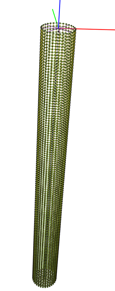
Figure 6 Frame consisting of “Beam” elements to ensure structural stiffness.
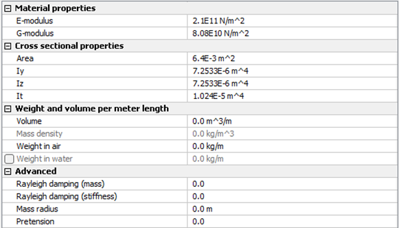
Figure 7.1 Properties of “Beam” elements in frame.
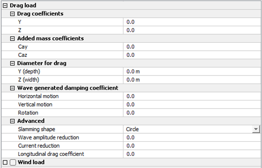
Figure 7.2 Properties of “Beam” elements in frame.
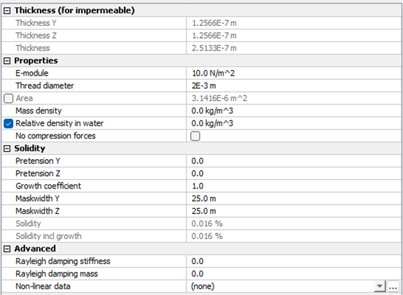
Figure 8.1 Material properties of “Membrane” elements corresponding to the structure surface.
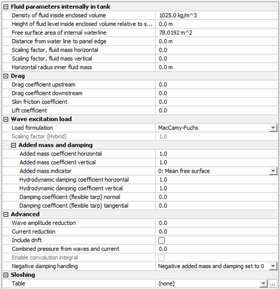
Figure 8.2 Material properties of “Membrane” elements corresponding to the structure surface.
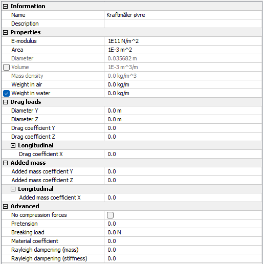
Figure 9 Properties of “Truss” in analysis model.